Revealer RDIC-3D Digital Image Correlation System for Quasi-Static Strain Measurement
| Brand | Revealer |
|---|---|
| Origin | Anhui, China |
| Manufacturer Type | Authorized Distributor |
| Origin Category | Domestic (China) |
| Model | RDIC-3D |
| Pricing | Available Upon Request |
| Camera Resolution | 20 MP (per camera) |
| Configuration | Dual high-resolution cameras, hardware synchronization controller, calibration target, proprietary DIC software suite, dedicated graphics workstation |
| Measurement Capability | Full-field 3D coordinates, quasi-static displacement, and strain tensors (εₓₓ, εᵧᵧ, ε_zz, γₓᵧ, γ_yz, γ_zx) |
Overview
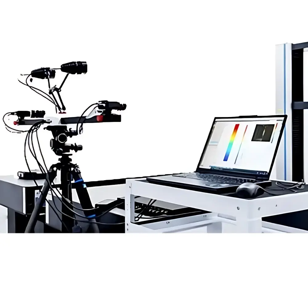
The Revealer RDIC-3D Digital Image Correlation (DIC) System is an engineered solution for non-contact, full-field quasi-static deformation analysis in solid mechanics research and industrial material testing. Based on stereo-DIC principles, the system captures synchronized high-fidelity images from two calibrated wide-baseline cameras, reconstructing surface topology and tracking sub-pixel-level pattern displacements across loaded specimens. Unlike point-wise sensors (e.g., strain gauges or LVDTs), RDIC-3D delivers spatially continuous strain tensor fields—enabling quantification of localized stress concentrations, crack initiation zones, and heterogeneous deformation behavior under controlled mechanical loading. Designed for laboratory-scale quasi-static conditions (loading rates typically < 0.1 mm/min), it supports both tensile, compression, bending, and creep test configurations when integrated with universal testing machines (UTMs) or custom fixtures.
Key Features
- Dual-camera stereo architecture with 20-megapixel global-shutter CMOS sensors, optimized for high signal-to-noise ratio and low geometric distortion
- Hardware-synchronized triggering ensures temporal coherence between image pairs, eliminating motion blur artifacts during slow-load experiments
- Proprietary calibration algorithm compliant with ISO/IEC 17025 traceability requirements for spatial measurement uncertainty estimation
- Real-time 3D point cloud generation and post-processing strain mapping (normal strains εₓₓ, εᵧᵧ, ε_zz; shear strains γₓᵧ, γ_yz, γ_zx)
- Robust subset-based correlation engine with adaptive grid refinement for heterogeneous surface patterns and large-deformation regimes
- Integrated thermal drift compensation module for extended-duration quasi-static tests (≥30 min)
Sample Compatibility & Compliance
The RDIC-3D system accommodates specimens ranging from 10 mm × 10 mm to 500 mm × 500 mm (field-of-view dependent), provided surfaces exhibit sufficient stochastic speckle contrast (achieved via spray-on or printed random patterns). It supports metallic alloys, composites, polymers, concrete, and biological tissues—provided optical access and surface stability are maintained during loading. The system complies with ASTM E837 (strain gauge validation methodology) for cross-validation of local strain measurements and aligns with ISO 10360-8 for optical coordinate measuring machine (CMM) performance verification. All raw image data, calibration logs, and processing parameters are stored with timestamped metadata to support GLP/GMP audit readiness and FDA 21 CFR Part 11-compliant electronic records when deployed in regulated environments.
Software & Data Management
The RDIC-3D Control & Analysis Suite provides a unified interface for acquisition, calibration, reconstruction, and quantitative reporting. Calibration routines follow Zhang’s method with lens distortion correction and epipolar geometry validation. Post-processing includes rigid-body motion subtraction, strain smoothing via Gaussian kernel convolution (user-defined sigma), and export of ASCII, CSV, and HDF5 formats for third-party finite element validation (e.g., Abaqus, ANSYS). Audit trails record all user actions—including parameter changes, ROI selections, and export events—with operator ID and timestamp. Software binaries are validated against NIST-traceable test datasets, and version history is maintained per ICH-GCP documentation standards.
Applications
- Constitutive model validation for hyperelastic, viscoelastic, and plastic materials under monotonic loading
- Microstructural strain localization analysis in fiber-reinforced composites and additively manufactured lattice structures
- Interface debonding and delamination onset detection in adhesive joints and layered systems
- Residual stress mapping after thermal cycling or shot peening via incremental hole-drilling correlation
- Educational use in advanced mechanics laboratories for visualizing Saint-Venant’s principle and stress concentration factors
FAQ
What is the typical measurement uncertainty for in-plane displacement at 100 mm field of view?
Under optimal lighting and speckle conditions, displacement uncertainty is ≤0.01 px (≈0.5 µm), as verified per ISO 10360-8 Annex D.
Can the system be used with existing universal testing machines?
Yes—hardware trigger outputs synchronize with UTM load-cell and extensometer signals via TTL or analog voltage inputs.
Is real-time strain visualization supported during acquisition?
No—strain computation occurs offline to ensure numerical convergence and tensor consistency; however, live 3D point cloud preview is available.
Does the software support batch processing of multiple test sequences?
Yes—scriptable workflows enable automated calibration application, subset size optimization, and report generation across datasets.
What documentation is provided for regulatory submissions?
A complete IQ/OQ protocol package—including installation checklist, operational verification scripts, and uncertainty budget templates—is supplied with each system.


