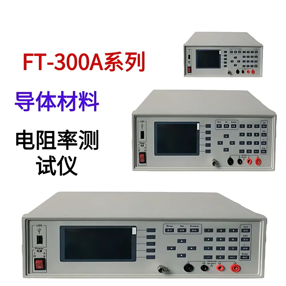
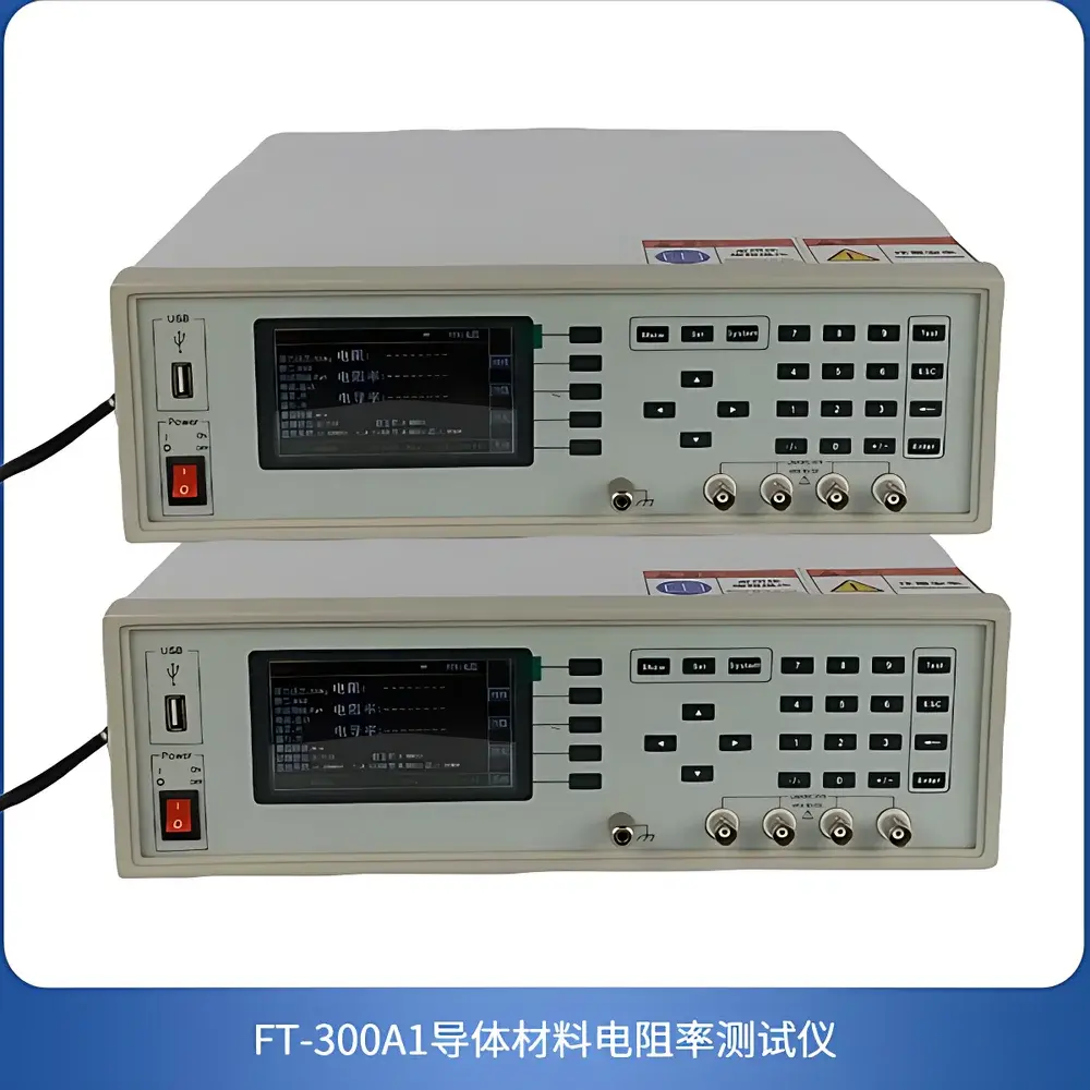
ROOKO FT-320A Metal Resistivity & Conductivity Tester
| Brand | ROOKO |
|---|---|
| Model | FT-320A |
| Measurement Principle | Four-terminal (Kelvin) DC resistance method |
| Resistivity Range | 2×10⁻⁸ – 20 kΩ·cm |
| Resistance Range | 0.01 μΩ – 20 kΩ |
| Voltage Ranges | 2 mV / 20 mV / 200 mV / 2 V (min. resolution: 0.1 μV at 2 mV range) |
| DC Constant Current Sources | 100 μA – 10 A (accuracy: ±0.1% for ≤100 mA |
| Temperature Sensing Accuracy | ±0.1 °C |
| Software Output | Volume resistivity, mass resistivity, conductivity, resistance per unit length, DC resistance ratio, temperature, current, voltage |
| Compliance | GB/T 351–2019 (replacing GB/T 351–1995) |
| Dimensions | 330 × 340 × 120 mm (W × D × H) |
| Power Supply | AC 220 V ±10%, 50 Hz |
Overview
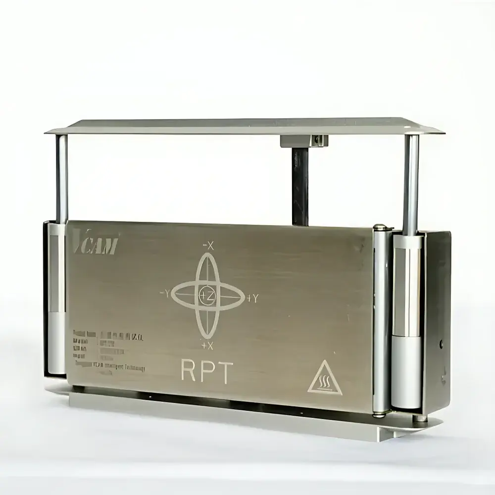
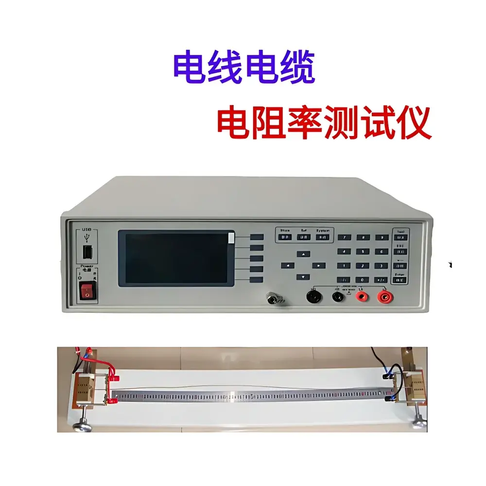
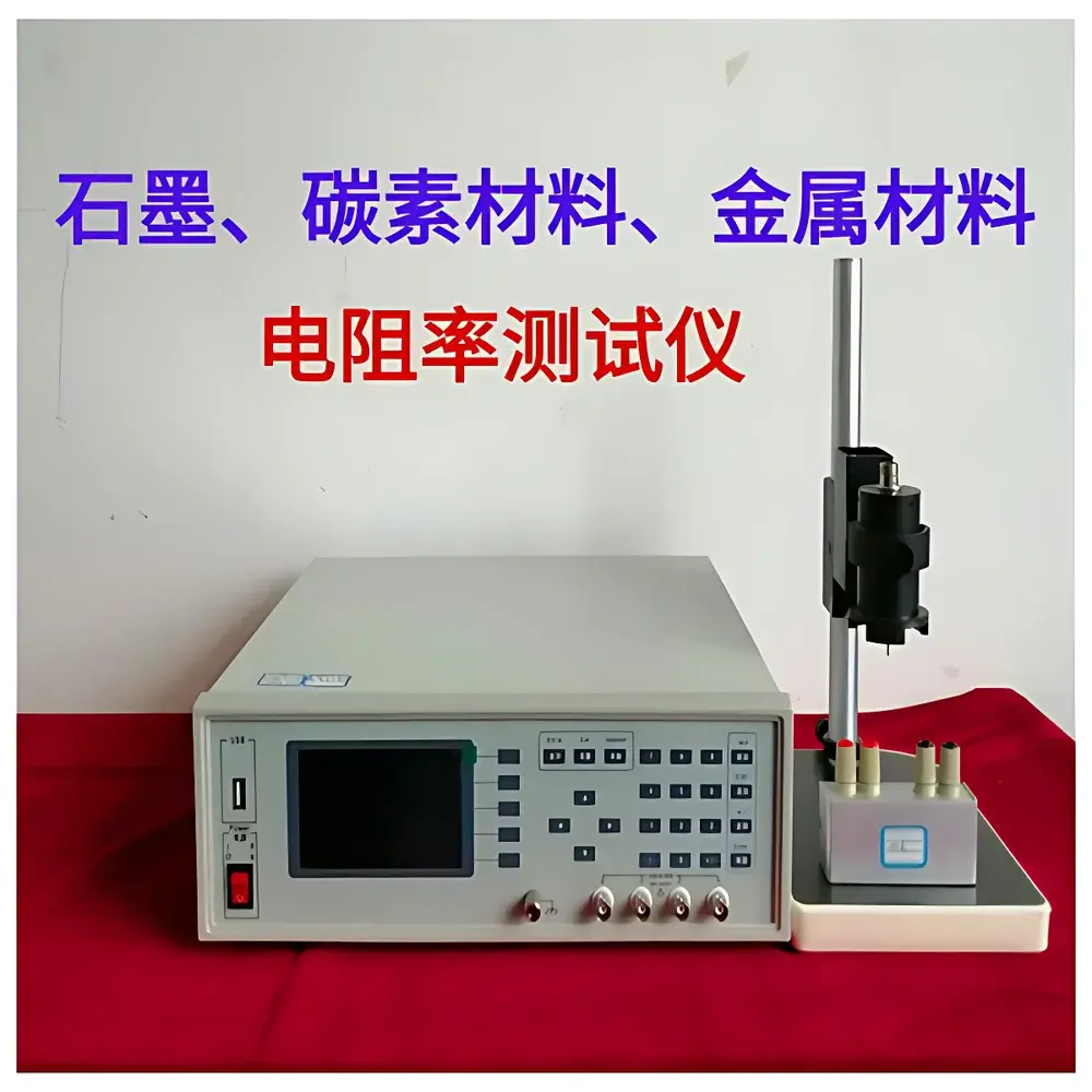
The ROOKO FT-320A Metal Resistivity & Conductivity Tester is a precision four-terminal (Kelvin) DC resistance measurement system engineered for accurate characterization of bulk electrical transport properties in metallic and metallurgical materials. It operates on the fundamental principle of applying a known, stable DC current through a specimen while simultaneously measuring the resulting potential drop across a defined, non-contact voltage-sensing section—eliminating lead and contact resistance errors. Designed in strict accordance with GB/T 351–2019 (“Methods for Measurement of Electrical Resistivity of Metallic Materials”), the instrument delivers traceable, reproducible results for volume resistivity (ρ, Ω·cm), mass resistivity (ρₘ, Ω·g/cm²), conductivity (σ, %IACS or S/m), resistance per unit length (R′, Ω/m), and DC resistance ratio—critical parameters for quality control in wire drawing, rod production, alloy development, and heat treatment validation.
Key Features
- Four-terminal Kelvin configuration with precision knife-edge voltage probes ensuring mechanical alignment parallel to each other and perpendicular to the specimen axis—meeting GB/T 351–2019 geometric requirements for probe spacing (≥1.5× specimen perimeter between adjacent current/voltage terminals).
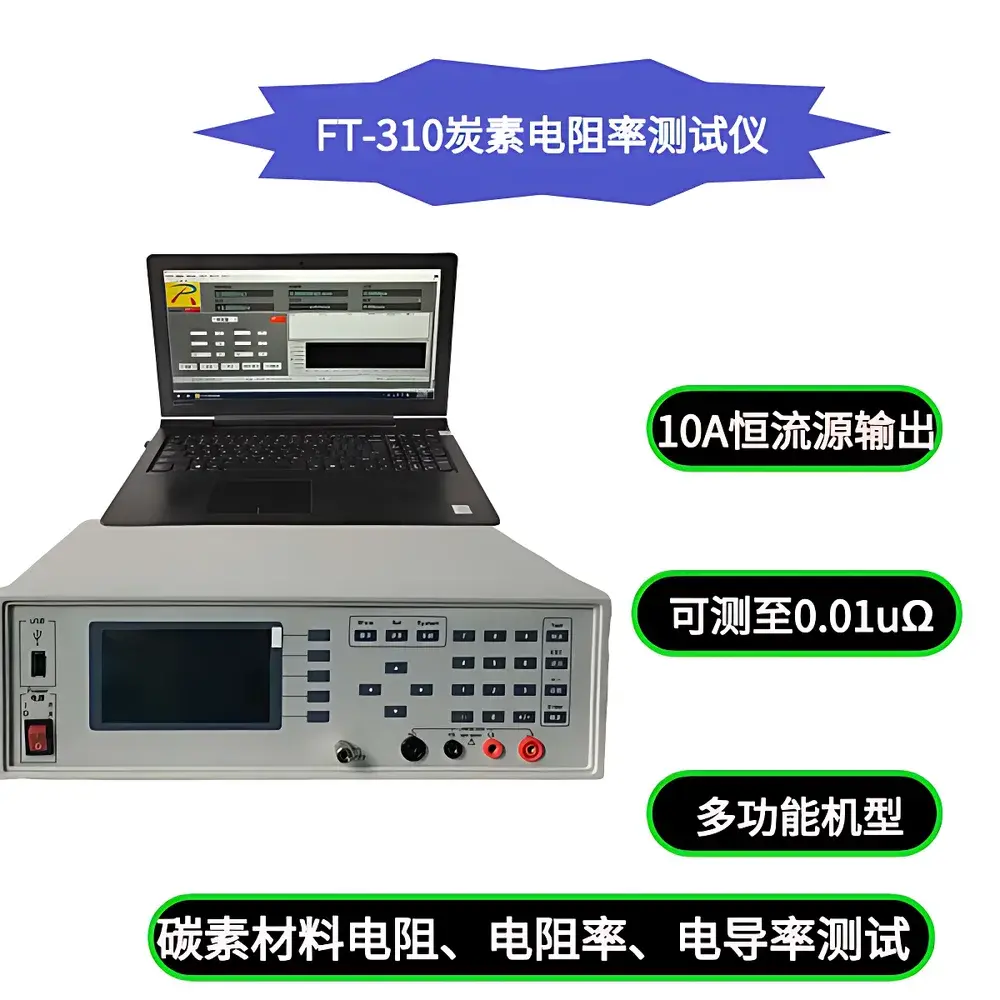
- Seven-step programmable DC constant current source (100 μA to 10 A) with high-stability feedback regulation and calibrated accuracy of ±0.1% (up to 100 mA) and ±0.15% (1 A/10 A), enabling optimal excitation for low-resistance metals (e.g., Cu, Al) and higher-resistivity alloys (e.g., stainless steels, Ni-based superalloys).
- High-resolution nanovolt-level voltage measurement: 0.1 μV resolution at the 2 mV range, with total error of 0.1% of reading + 6 digits—critical for resolving minute resistivity differences in high-purity conductors.
- Integrated Pt100-class temperature sensor with ±0.1 °C accuracy, enabling automatic temperature compensation to standard 20 °C reference conditions as mandated by GB/T 351–2019.
- Embedded microprocessor-controlled architecture with real-time calculation of derived parameters—including %IACS (International Annealed Copper Standard), mass resistivity, and DC resistance ratio—without external computation.
Sample Compatibility & Compliance
The FT-320A accommodates solid metallic specimens in bar, rod, wire, and sheet forms with standardized cross-sectional geometries. Its modular夹具 (optional custom fixture package) supports variable sample lengths and diameters while maintaining compliance with probe placement rules defined in GB/T 351–2019. The system is not intended for liquid, gaseous, or powdered samples—those require dedicated four-point probe or van der Pauw configurations outside this model’s scope. While GB/T 351–2019 is the primary normative reference, the underlying measurement methodology aligns with internationally recognized practices in ASTM B193 (Standard Test Method for Resistivity of Electrical Conductor Materials) and IEC 60468 (Electrical resistance of metallic materials). Data integrity meets GLP-aligned documentation requirements, with timestamped, parameter-tagged output suitable for internal QC records.
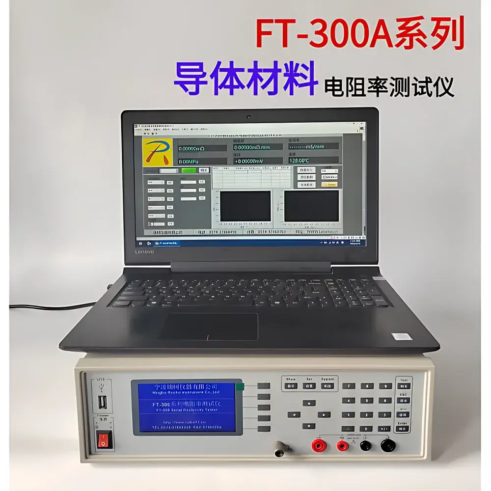
Software & Data Management
The included PC-based software provides real-time graphical display and tabular export (CSV, Excel-compatible) of all measured and calculated parameters: volume resistivity (Ω·cm), mass resistivity (Ω·g/cm²), conductivity (%IACS or S/m), resistance per unit length (Ω/m), DC resistance ratio, temperature (°C), applied current (A), and sensed voltage (V). Each dataset is automatically annotated with test date, operator ID (user-definable), ambient temperature, and calibration status flags. Exported files contain no proprietary binary encoding—ensuring long-term readability and compatibility with LIMS or statistical process control (SPC) platforms. Audit trail functionality records all parameter changes and measurement initiations, supporting basic traceability requirements under ISO/IEC 17025 Clause 7.7.
Applications
- Quality assurance of copper and aluminum conductors in cable and busbar manufacturing.
- Verification of annealing effectiveness in cold-worked stainless steel strips.
- Batch-to-batch consistency checks for titanium alloy rods used in aerospace forging.
- Resistivity mapping along drawn wire lengths to detect localized microstructural anomalies.
- Validation of grain size effects on electron scattering in high-purity nickel foils.
- Supporting material certification packages required by ASME BPVC Section II Part D or EN 10002-1.
FAQ
What standards does the FT-320A comply with?
It conforms fully to GB/T 351–2019 and implements measurement geometry and uncertainty protocols consistent with ASTM B193 and IEC 60468.
Can it measure thin films or coatings?
No—the FT-320A is designed exclusively for bulk metallic specimens with defined cross-sections; thin-film resistivity requires four-point probe systems with micropositioning stages.
Is temperature compensation automatic?
Yes—integrated Pt100 sensing enables real-time correction to 20 °C reference conditions per GB/T 351–2019 Annex A.
Does the software support FDA 21 CFR Part 11 compliance?
The base software provides audit-ready data logs but lacks electronic signature, role-based access, and full Part 11 validation packages—custom validation services are available upon request.
What is the minimum resolvable resistivity difference for copper wire?
At 20 °C, with 10 A excitation and 2 mV range, the system resolves <0.005% IACS variation in 99.99% Cu (ρ ≈ 1.678 μΩ·cm), assuming optimal contact and geometry.