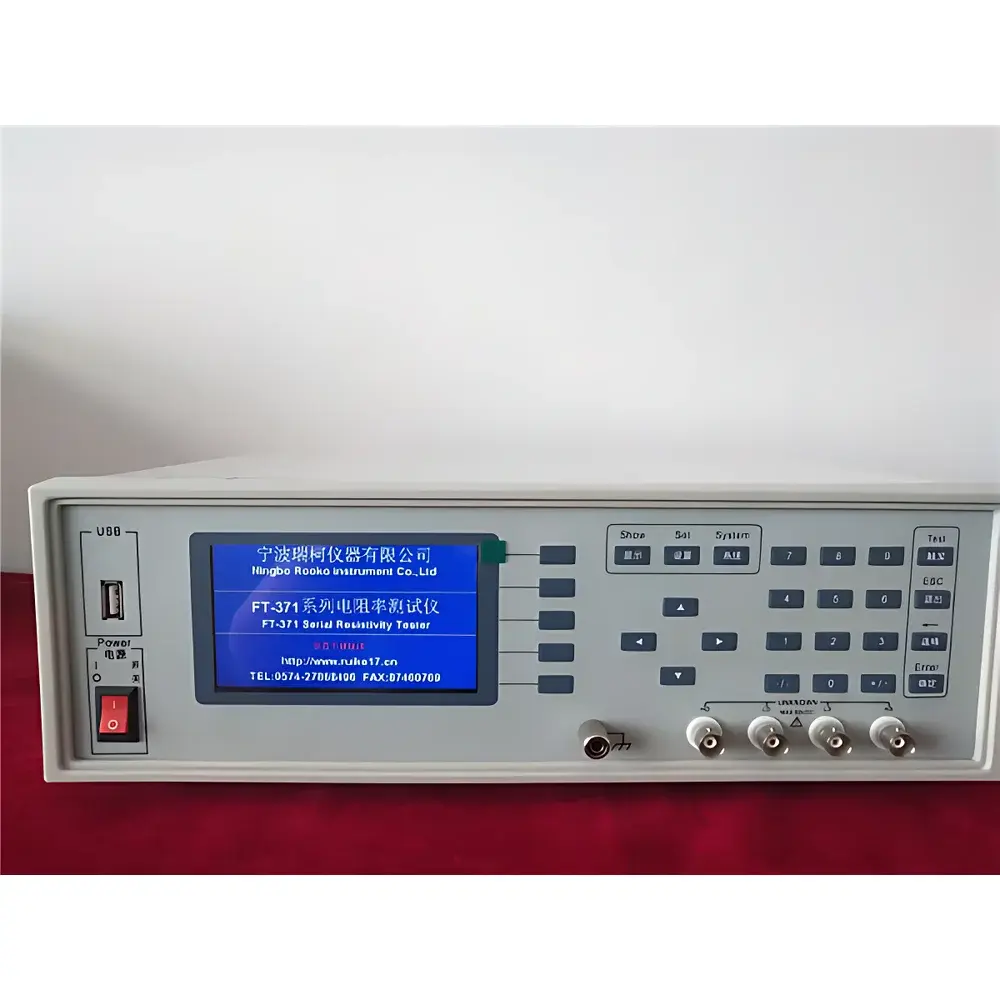
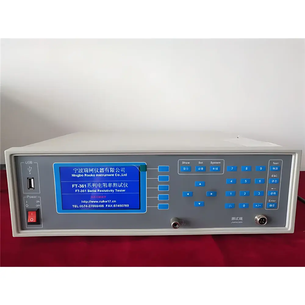
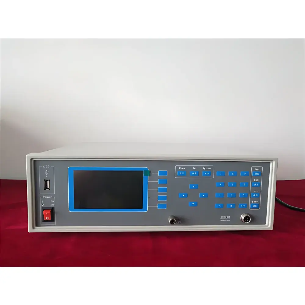

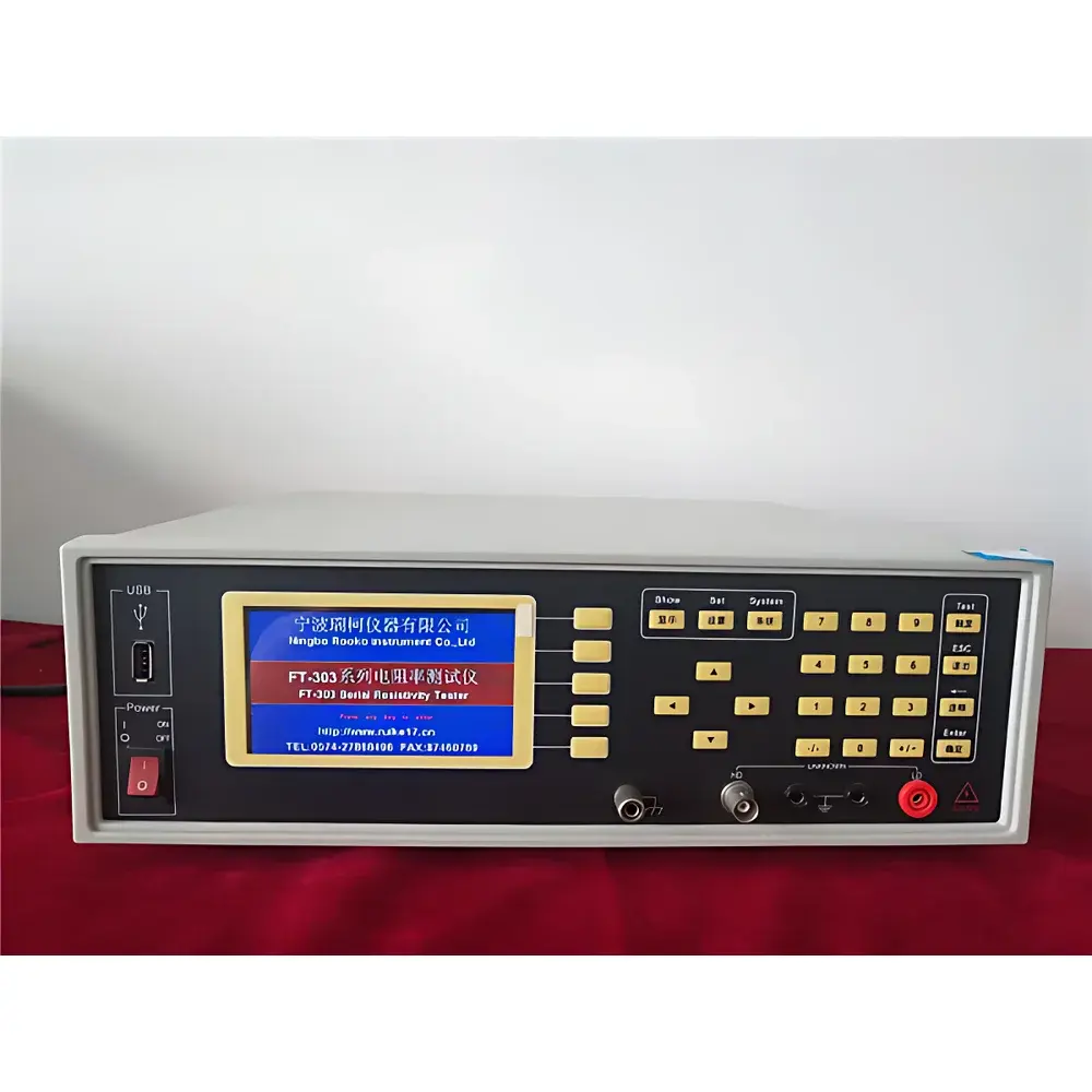
ROOKO FT-361 Dual-Measurement Low-Resistance Four-Point Probe Tester
| Brand | ROOKO |
|---|---|
| Model | FT-361 |
| Origin | Zhejiang, China |
| Automation Level | Manual |
| Compliance | GB/T 1551–2018 (Silicon Single Crystal Resistivity Test Method), ASTM F84–20 |
| Sheet Resistance Range | 10⁻⁶–2×10² Ω/□ |
| Resistivity Range | 10⁻⁷–2×10³ Ω·cm |
| Test Current | 0.1 μA, 1 μA, 10 μA, 100 μA |
| Current Accuracy | ±0.1% of reading |
| Resistance Measurement Accuracy | ≤0.3% |
| Overall System Uncertainty | ≤4% (verified against NIST-traceable standard wafers) |
| Probe Spacing Options | 1 mm, 2 mm, 3 mm |
| Probe Tip Materials | Tungsten Carbide, Stainless Steel, Gold-Plated Phosphor Bronze Hemispherical Tips |
| Display | 4.3-inch TFT LCD showing R, ρ, Rₛ, T, σ, d, αₜ, V, I, probe geometry, spacing, thickness, unit conversion |
| Power Input | AC 220 V ±10%, 50 Hz |
| Max Power Consumption | <30 W |
| Optional Accessories | PC control software (with audit trail & CSV/PDF export), square probe head, linear probe head, motorized XYZ test stage, thermal chamber interface kit |
Overview
The ROOKO FT-361 Dual-Measurement Low-Resistance Four-Point Probe Tester is an engineered solution for precise sheet resistance (Rs) and volume resistivity (ρ) characterization of thin conductive and semiconducting films—particularly those exhibiting ultra-low resistance values down to 1 µΩ/□. It operates on the fundamental principle of the four-point probe method, where two outer probes inject a known constant current (I) while two inner probes measure the resulting voltage drop (V), eliminating contact resistance and lead wire effects. The FT-361 implements dual-measurement mode: by reversing current and voltage probe roles and averaging results, it inherently corrects for geometric asymmetry, probe misalignment, edge effects, and non-uniform current distribution—critical for accurate measurement of small-area samples, patterned films, or irregular substrates. Designed in strict accordance with GB/T 1551–2018 and referencing ASTM F84–20 standards, the instrument supports traceable metrology workflows in R&D labs, process development lines, and quality assurance environments across semiconductor fabrication, photovoltaics, flexible electronics, and advanced materials research.
Key Features
- Dual-measurement architecture with automatic probe polarity switching and arithmetic averaging to suppress systematic errors from probe spacing deviation, sample boundary proximity, and tip wear.
- High-resolution constant-current source with selectable ranges (0.1 µA to 100 µA) and ±0.1% reading accuracy, optimized for low-noise measurement of highly conductive layers without Joule heating artifacts.
- Integrated temperature sensor with real-time coefficient-based resistivity compensation (αT), enabling quantitative correction for thermal drift during extended measurements or environmental testing.
- 4.3-inch high-contrast TFT LCD interface displaying 12 simultaneous parameters: sheet resistance (Ω/□), resistivity (Ω·cm), conductivity (S/cm), thickness (µm), temperature (°C), voltage (mV), current (µA), probe geometry (linear/square), probe spacing (mm), material type flag, unit conversion status, and temperature coefficient.
- Auto-ranging function with intelligent scale selection—no manual range switching required; system automatically selects optimal current and gain settings based on preliminary voltage feedback.
- Modular probe head design supporting interchangeable tungsten carbide, stainless steel, and gold-plated phosphor bronze hemispherical tips—each certified for ≤0.5 µm tip radius tolerance and ≥10⁶ actuation cycles.
Sample Compatibility & Compliance
The FT-361 accommodates rigid and flexible substrates up to 200 mm × 200 mm using optional XYZ positioning stages. It is validated for use with ITO-coated glass, sputtered metal films (Al, Cu, Ag), printed conductive inks, CVD graphene transfers, PEDOT:PSS layers, EMI shielding fabrics, conductive elastomers, and doped silicon wafers. All electrical safety and EMC performance comply with IEC 61010-1:2010 for laboratory measurement equipment. Data integrity meets GLP/GMP-aligned requirements when paired with optional PC software featuring 21 CFR Part 11-compliant audit trails, electronic signatures, and immutable data logging. Calibration verification follows ISO/IEC 17025 principles using certified reference standards (e.g., NIST SRM 2135a, NIST SRM 2136) traceable to national metrology institutes.
Software & Data Management
The optional ROOKO DataMaster™ PC software provides full remote instrument control via USB 2.0 or RS-232. It enables automated multi-point mapping (grid or custom coordinate input), time-series monitoring under thermal stress (when integrated with environmental chambers), statistical analysis (mean, std dev, CPK), and batch report generation in PDF/CSV formats. All raw data—including timestamps, operator ID, ambient temperature/humidity metadata, and calibration certificate IDs—are embedded into each exported file. Software logs include full audit trail records compliant with FDA 21 CFR Part 11 for regulated environments, including user login/logout events, parameter changes, and measurement deletions—with no ability to alter historical entries.
Applications
- Process validation of transparent conductive oxide (TCO) deposition in flat-panel display and solar cell manufacturing.
- Quality screening of roll-to-roll coated antistatic films, conductive adhesives, and printed electronics inks.
- Resistivity profiling across diffusion junctions, epitaxial layers, and ion-implanted regions in Si and compound semiconductor wafers.
- Thickness-independent sheet resistance evaluation of ultra-thin (<50 nm) metallic interconnects and 2D material heterostructures.
- EMI shielding effectiveness correlation studies via surface conductivity mapping on composite laminates and textile substrates.
- R&D quantification of thermal coefficient of resistance (TCR) in thermoelectric thin films under controlled temperature ramps.
FAQ
What standards does the FT-361 comply with?
It conforms to GB/T 1551–2018 for silicon crystal resistivity testing and aligns with ASTM F84–20 for four-point probe methodology. Electrical safety and EMC meet IEC 61010-1:2010.
Can the FT-361 measure samples below 1 µΩ/□?
No—the specified lower limit is 1 µΩ/□. For sub-microohm measurements, a micro-ohmmeter with Kelvin sensing or superconducting quantum interference device (SQUID)-based systems are recommended.
Is probe spacing calibration required before each test?
No. The instrument applies geometric correction algorithms based on user-input probe spacing (1/2/3 mm); however, physical probe spacing must be verified annually using a NIST-traceable micrometer gauge.
Does the system support GLP-compliant reporting?
Yes—when used with the optional DataMaster™ software, it delivers full 21 CFR Part 11 compliance including electronic signatures, audit trails, and data immutability.
Can I integrate the FT-361 with environmental test chambers?
Yes—via the optional thermal chamber interface kit, which provides isolated analog I/O for synchronized temperature feedback and probe actuation control during in-situ resistivity monitoring.