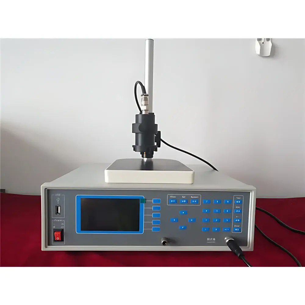
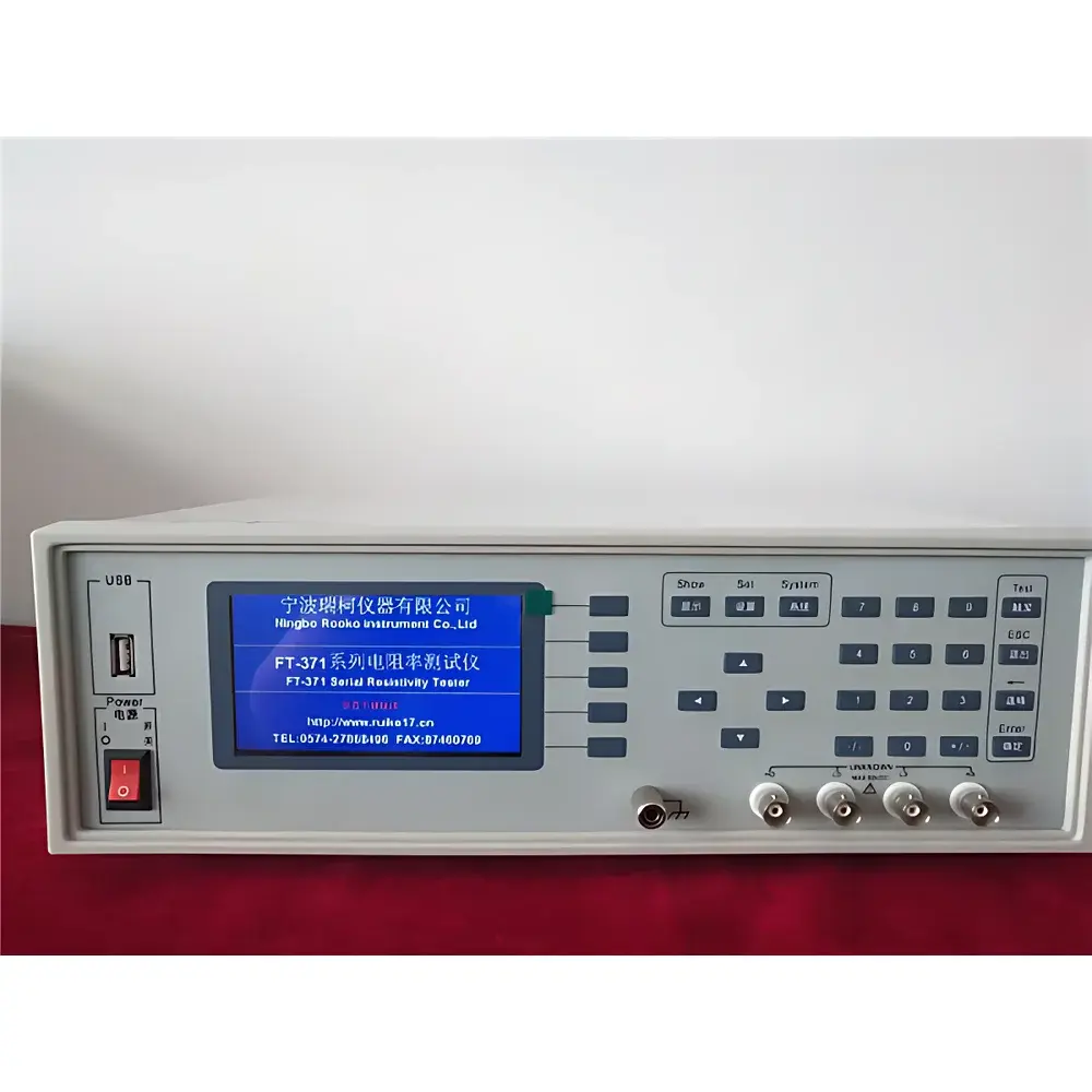
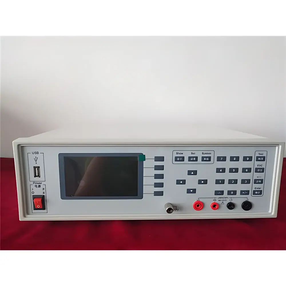

ROOKO FT-371 Dual-Measurement Four-Point Probe Sheet Resistance Tester for High-Resistivity Semiconductor Thin Films
| Brand | ROOKO |
|---|---|
| Origin | Zhejiang, China |
| Model | FT-371 |
| Measurement Range | 10¹–2×10¹⁰ Ω/□ |
| Resistivity Range | 10²–2×10¹¹ Ω·cm |
| Test Current | 1 mA – 1 pA |
| Current Accuracy | ±0.1% of reading |
| Resistance Accuracy | ≤5% (≤10⁸ Ω), ≤20% (>10⁸ Ω) |
| Display | 4.3" LCD showing R, ρ, Rₛ, T, σ, probe geometry, spacing, thickness, temp. coeff., I/V |
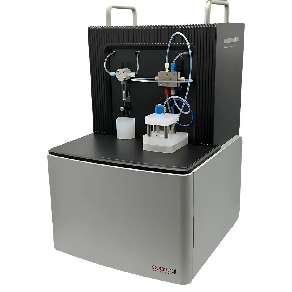
| Measurement Method | Dual-electrode four-point probe (linear or square configuration) |
| Power Supply | AC 220 V ±10%, 50 Hz, <30 W |
| Overall Uncertainty | ≤4% (certified standard sample) |
| Optional Accessories | PC control software, square probe head, linear probe head, temperature-controlled test platform, probe spacing (1/2/3 mm), probe tip materials (tungsten carbide, stainless steel, gold-plated phosphor bronze hemispherical) |
Overview
The ROOKO FT-371 is a dual-measurement four-point probe instrument engineered for precise sheet resistance (Rs) and volume resistivity (ρ) characterization of thin conductive and semiconducting films—particularly those exhibiting high to ultra-high resistivity. It operates on the fundamental principle of the van der Pauw–four-point probe method, where two outer probes inject a known current while two inner probes measure the resulting voltage drop, eliminating contact resistance and lead-wire errors. The FT-371 implements true dual-electrode switching: it performs two sequential measurements with reversed current/voltage probe assignments and computes an averaged result, thereby compensating for geometric non-uniformity, edge effects, probe misalignment, and mechanical drift—critical for accurate Rs quantification on small-area or irregular substrates such as sputtered ITO layers, evaporated Al films, EMI shielding coatings, and doped semiconductor wafers. Its extended measurement range up to 2 × 10¹⁰ Ω/□ enables reliable evaluation of low-conductivity functional films used in flexible electronics, radiation-shielding windows, and high-temperature sensor elements.
Key Features
- Dual-electrode four-point probe architecture compliant with GB/T 1551–2018 (Chinese national standard for monocrystalline silicon resistivity testing) and aligned with ASTM F84–22 guidelines for sheet resistance measurement.
- Auto-ranging DC current source (1 mA to 1 pA) with ±0.1% reading accuracy and programmable step resolution, ensuring stable excitation across six decades of resistance.
- Integrated temperature compensation algorithm and real-time thermal monitoring via built-in sensor; supports optional integration with environmental chambers for controlled-temperature Rs profiling from –40 °C to +200 °C.
- 4.3-inch high-contrast LCD interface displaying simultaneous readouts of sheet resistance (Ω/□), resistivity (Ω·cm), conductivity (S/cm), temperature (°C), probe geometry, spacing (1/2/3 mm), film thickness (user-input), and temperature coefficient of resistance (TCR).
- Modular probe head design: interchangeable linear or square configurations with selectable tungsten carbide, stainless steel, or gold-plated phosphor bronze hemispherical tips—optimized for soft polymer films, brittle ceramics, or metallized papers without surface damage.
- Self-calibrating AD conversion circuitry with ≤4% total measurement uncertainty (verified against NIST-traceable standard reference samples).
Sample Compatibility & Compliance
The FT-371 accommodates a broad spectrum of planar conductive materials including but not limited to: sputtered ITO and AZO transparent electrodes; evaporated aluminum and chromium thin films; printed conductive inks (Ag, Cu, carbon-based); electroplated PCB copper foils; conductive adhesives and elastomers; antistatic polymer sheets; EMI-absorbing composites; and diffusion layers on Si, GaAs, or SiC wafers. Its probe geometry flexibility allows validation per ISO 11359-2 for polymer conductivity, ASTM D257 for insulating materials, and SEMI MF1530 for semiconductor wafer metrology. While not FDA 21 CFR Part 11–certified out-of-the-box, the optional PC software module supports audit-trail-enabled data logging suitable for GLP/GMP-aligned quality control environments when deployed with timestamped user authentication and electronic signature protocols.
Software & Data Management
An optional Windows-compatible software suite enables remote instrument control, automated multi-point mapping, and batch data export in CSV, XLSX, and PDF formats. The software logs full parameter metadata—including probe type, spacing, thickness input, ambient temperature, and measurement timestamp—for traceability. It generates standardized reports compliant with internal QC templates or customer-specific format requirements. All raw voltage/current pairs are retained for post-hoc reanalysis, and calibration constants can be archived per probe set to maintain long-term measurement integrity across maintenance cycles.
Applications
- Process development and incoming inspection of conductive coatings in photovoltaic cell manufacturing (e.g., front-side Ag paste, rear-side Al alloy layers).
- Quality assurance of flexible touch sensor films (resistive/capacitive), including PET-ITO laminates and printed graphene electrodes.
- R&D characterization of novel thermoelectric thin films, 2D material heterostructures (MoS₂, WS₂), and ion-conducting solid electrolytes.
- Failure analysis of delamination-induced resistivity gradients in metalized labels, RF shielding tapes, and aerospace-grade conductive composites.
- Educational use in university semiconductor physics and materials science laboratories for hands-on carrier concentration estimation via ρ–Rs–t correlation.
FAQ
What probe spacing options are supported, and how does spacing affect measurement validity?
The FT-371 supports 1 mm, 2 mm, and 3 mm probe spacings. Spacing selection must satisfy the condition t ≪ s (film thickness much less than probe spacing) for valid Rs interpretation; deviations require correction using the appropriate geometric factor from ASTM F84 Annex A.
Can this instrument measure bulk resistivity of thick wafers?
Yes—when combined with accurate thickness input and verified probe alignment, the FT-371 calculates volume resistivity ρ = Rs × t, applicable to single-crystal Si, Ge, or compound semiconductor substrates per GB/T 1551–2018.
Is temperature coefficient (TCR) calculation automated?
Yes—the instrument computes TCR from sequential Rs readings at two user-defined temperatures, assuming linear behavior over the tested interval.
Does the system support statistical process control (SPC) output?
When used with the optional software, it exports mean, standard deviation, Cp/Cpk, and control chart-ready datasets compatible with Minitab, JMP, or custom SPC platforms.
How is probe tip wear monitored and compensated?
The software allows storage of individual probe calibration offsets; periodic verification using certified standard films (e.g., 100 Ω/□ Si wafer) ensures ongoing traceability without hardware recalibration.