SPOTRON SP-3510 Digital Welding Parameter Analyzer for Resistance Spot & Seam Welding
| Brand | SPOTRON (TAMASAKI) |
|---|---|
| Origin | Japan |
| Model | SP-3510 |
| Measurement Principle | Rogowski coil-based current sensing + precision shunt/voltage divider |
| Current Range | 1.0–500 kA (RMS or peak) |
| Voltage Range | 0–60.0 V (RMS or peak) |
| Time Measurement | 0.5–9999 cycles (50/60 Hz) or 0.1–9999 ms |
| Accuracy | ±2% FS (current), ±1% FS (voltage), ±0.5 cycle / ±0.1 ms (time) |
| Display | 3.5″ TFT LCD touchscreen (240×320 pixels) |
| Data Storage | SD card (included), USB 2.0 host/device interface |
| Power | Rechargeable lead-acid battery + universal AC adapter (100–240 V, 50/60 Hz) |
| Dimensions | 145 × 183 × 65 mm |
| Weight | ~1.9 kg |
| Compliance | Designed for industrial welding process validation per ISO 14324, AWS D8.8, and JIS Z 3136 |
Overview
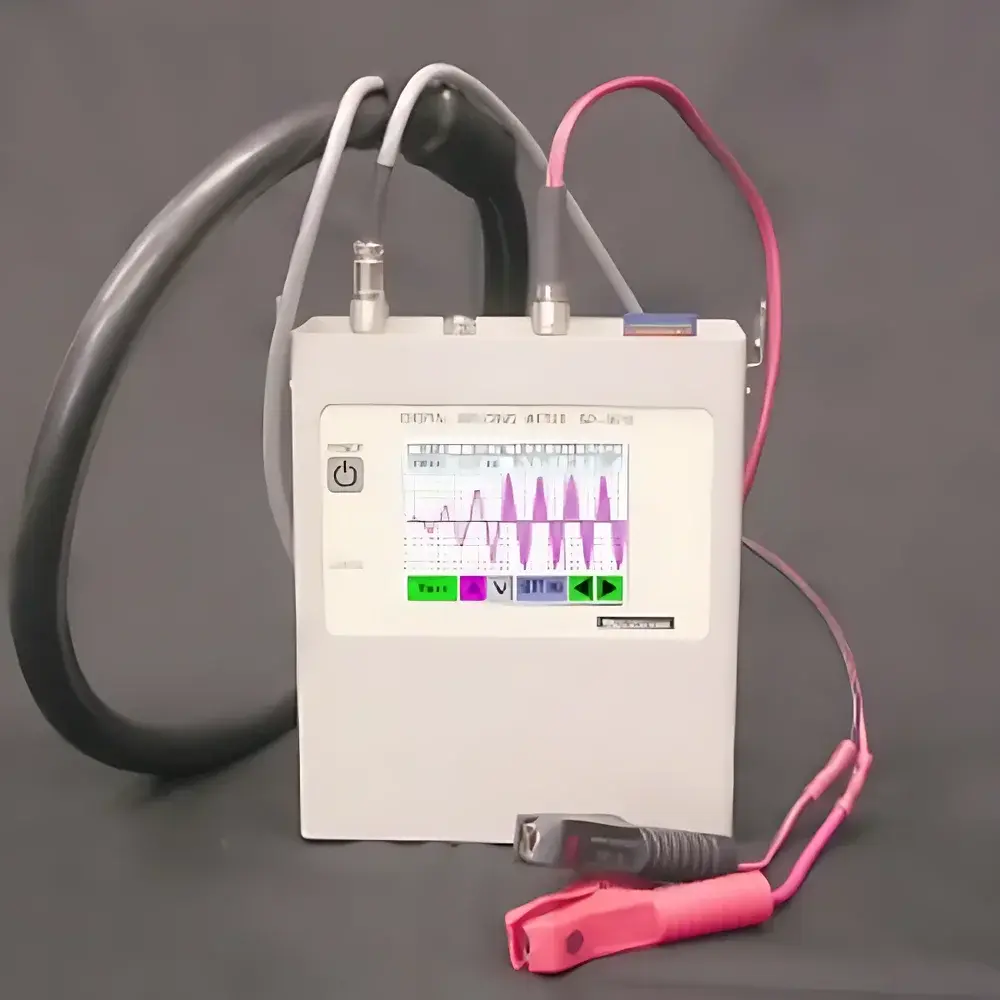
The SPOTRON SP-3510 is a dedicated digital welding parameter analyzer engineered for real-time, high-fidelity measurement and validation of critical electrical parameters in resistance spot and seam welding systems. Unlike general-purpose multimeters or analog pressure gauges — which are misclassified in the input taxonomy — the SP-3510 employs a calibrated Rogowski coil (PU-14) for non-intrusive, high-bandwidth current sensing on secondary welding circuits, coupled with isolated voltage measurement via clamp-style leads. Its core function is metrological verification of weld energy delivery: simultaneous acquisition of primary current (1.0–500 kA RMS/peak), secondary voltage (0–60.0 V RMS/peak), and precise time-domain metrics including total conduction time, peak time (Tp), and end-of-conduction time (Tz). The device operates independently of weld controller communication protocols, enabling vendor-agnostic process auditing — essential for automotive Tier-1 suppliers, aerospace component manufacturers, and ISO 9001-certified fabrication facilities requiring objective evidence of process consistency.
Key Features
- Four synchronized display modes: Standard (numerical readouts), Decomposed (cycle-by-cycle breakdown per weld event), Waveform (real-time current/voltage temporal profile), and Graphical (trended parameter history over multiple welds)
- 3.5-inch resistive touchscreen interface (240×320 px) with intuitive icon-driven navigation — no external keyboard or PC required for field configuration
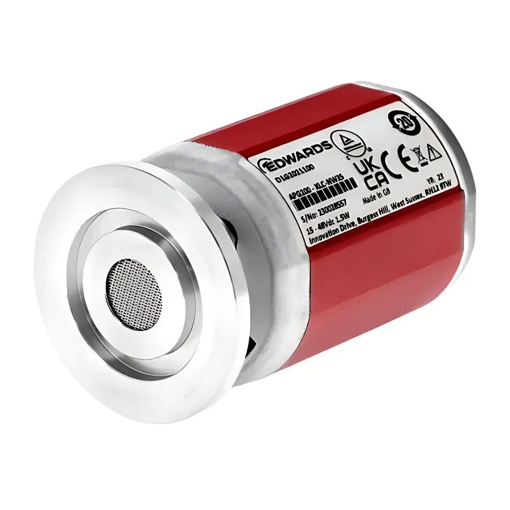
- High-dynamic-range current measurement using a flexible, toroidal PU-14 Rogowski sensor (Φ18 mm aperture, 800 mm loop length, ~Φ260 mm nominal diameter), optimized for low-phase-shift response up to 10 kHz bandwidth
- Time resolution down to ±0.1 ms for millisecond-scale timing validation, and ±0.5 cycle accuracy at line frequency (50/60 Hz) — supporting both short-duration spot welds and extended seam weld sequences up to 9999 cycles
- Dual power architecture: integrated rechargeable lead-acid battery (≥4 hours continuous operation) and universal AC adapter (100–240 V, 50/60 Hz) for lab or shop-floor deployment
- Onboard data sovereignty: All measurements — including raw waveforms — are timestamped and stored directly to included SD card; USB 2.0 port enables direct file transfer or connection to host PCs for automated report generation
Sample Compatibility & Compliance
The SP-3510 interfaces with all major resistance welding machine architectures: single-phase AC, single-phase rectified, three-phase rectified, inverter-controlled, and capacitor-discharge (CD) systems. It measures secondary-side parameters only — eliminating risk of high-voltage exposure while maintaining fidelity across waveform shapes (sinusoidal, pulsed DC, truncated sine). The device complies with electromagnetic compatibility requirements per IEC 61326-1 (industrial environment) and meets safety insulation standards per IEC 61010-1 CAT II 600 V. Its measurement methodology aligns with technical validation practices defined in ISO 14324 (resistance welding — quality assurance), AWS D8.8 (automotive welding specification), and JIS Z 3136 (Japanese standard for resistance welding equipment testing). Raw data files include embedded metadata (date/time, operator ID, weld sequence number) to support audit-ready documentation under GLP and IATF 16949 frameworks.
Software & Data Management
No proprietary software installation is required for basic operation or data retrieval. Timestamped CSV and binary waveform files (.spw) are written directly to SD card with hierarchical folder structure (e.g., /2024/06/15/WELD_001/). USB connectivity supports mass-storage mode for drag-and-drop access or MTP protocol for integration into enterprise MES/QMS platforms. Optional thermal printer (sold separately) provides immediate hardcopy of weld summaries with barcode-readable timestamps — useful for shop-floor traceability logs. For advanced analysis, third-party tools (e.g., MATLAB, Python Pandas, or LabVIEW) can import waveform data for FFT-based harmonic distortion assessment, energy integral (I²t) calculation, or statistical process control (SPC) charting. Audit trails are preserved via immutable SD card logging; no data resides in volatile memory after power-down.
Applications
- Pre-production weld schedule qualification: Verifying current/voltage profiles match simulation outputs prior to fixture release
- In-process monitoring on production lines: Detecting drift in transformer tap settings, electrode wear, or cable degradation through trended I²t deviation
- Root cause analysis of weld defects: Correlating voltage spikes, current asymmetry, or timing anomalies with nugget expulsion or indentation issues
- Supplier certification audits: Providing objective, instrument-calibrated evidence of process capability (Cpk/Ppk) for Tier-2 welding equipment vendors
- Welding engineer training: Visualizing real-world waveform distortions caused by magnetic blowout, phase imbalance, or rectifier failure
FAQ
Is the SP-3510 suitable for measuring primary-side welding current?
No. It is designed exclusively for secondary-circuit measurement using the supplied PU-14 Rogowski coil. Primary-side current requires a separate high-isolation CT rated for mains voltage.
Does the device support MODBUS or Ethernet communication?
No. It is a standalone analyzer with SD/USB data export only. Real-time streaming to SCADA requires external DAQ hardware.
Can waveform data be exported in MATLAB-compatible format?
Yes. Binary .spw files include header metadata and raw 16-bit samples; Python reference parsers and MATLAB import scripts are available from SPOTRON’s technical support portal.
What calibration interval is recommended?
Annual calibration against NIST-traceable standards is advised. The unit stores last-calibration date and technician ID in non-volatile memory.
Is the PU-14 coil compatible with robotic welding guns?
Yes — its flexible loop design allows routing around complex gun geometries, though minimum bend radius (Φ120 mm) must be observed to preserve phase accuracy.