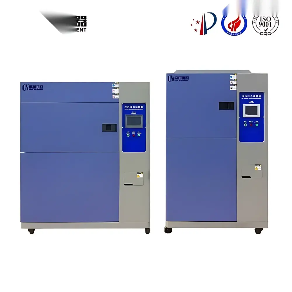
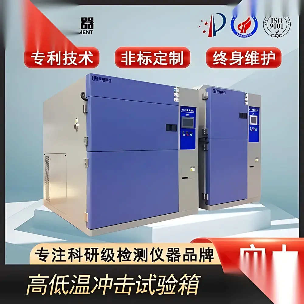
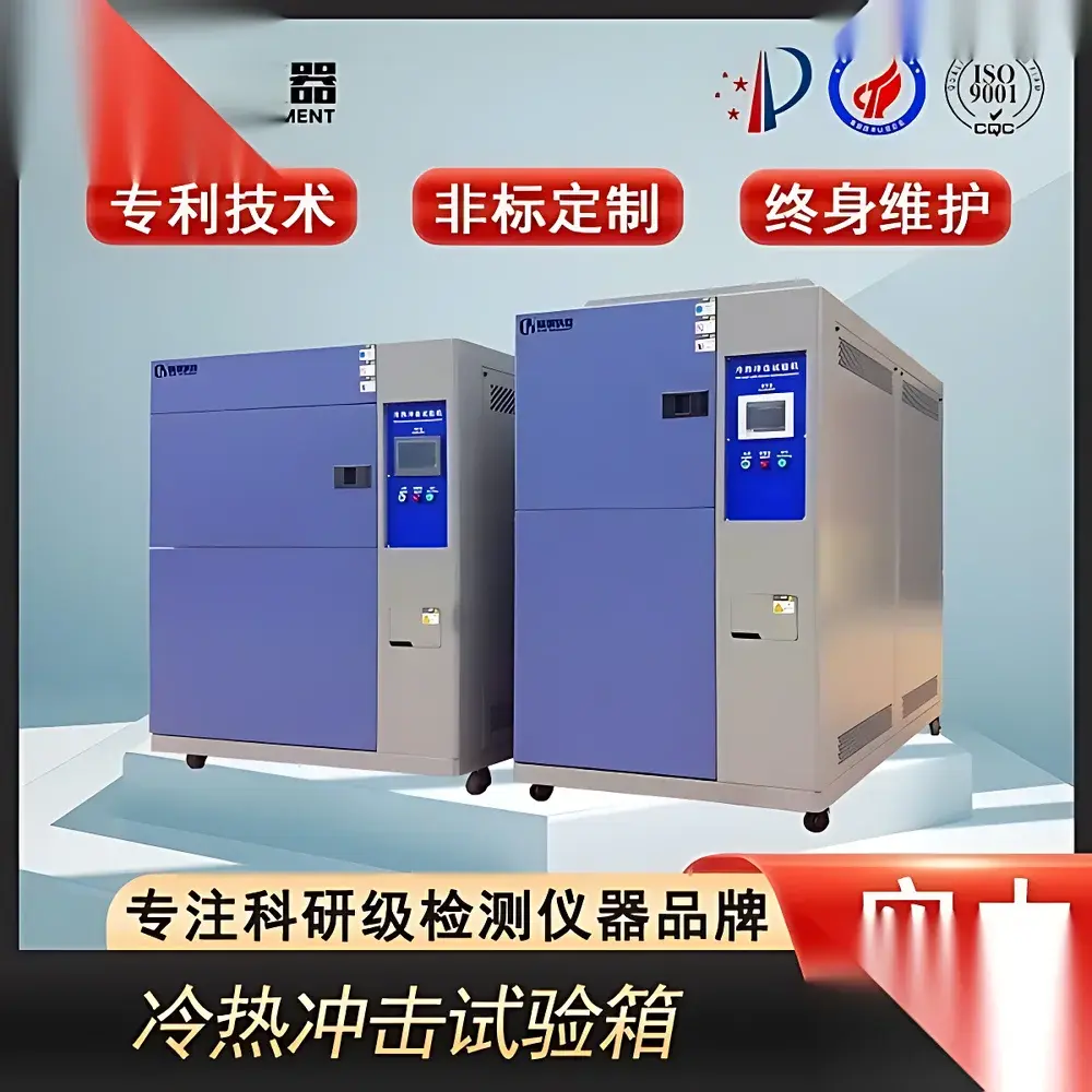
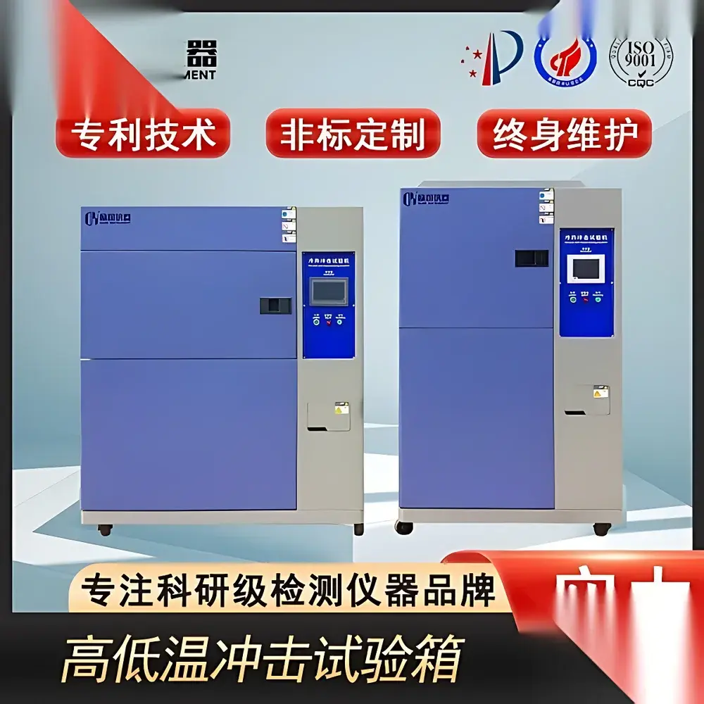
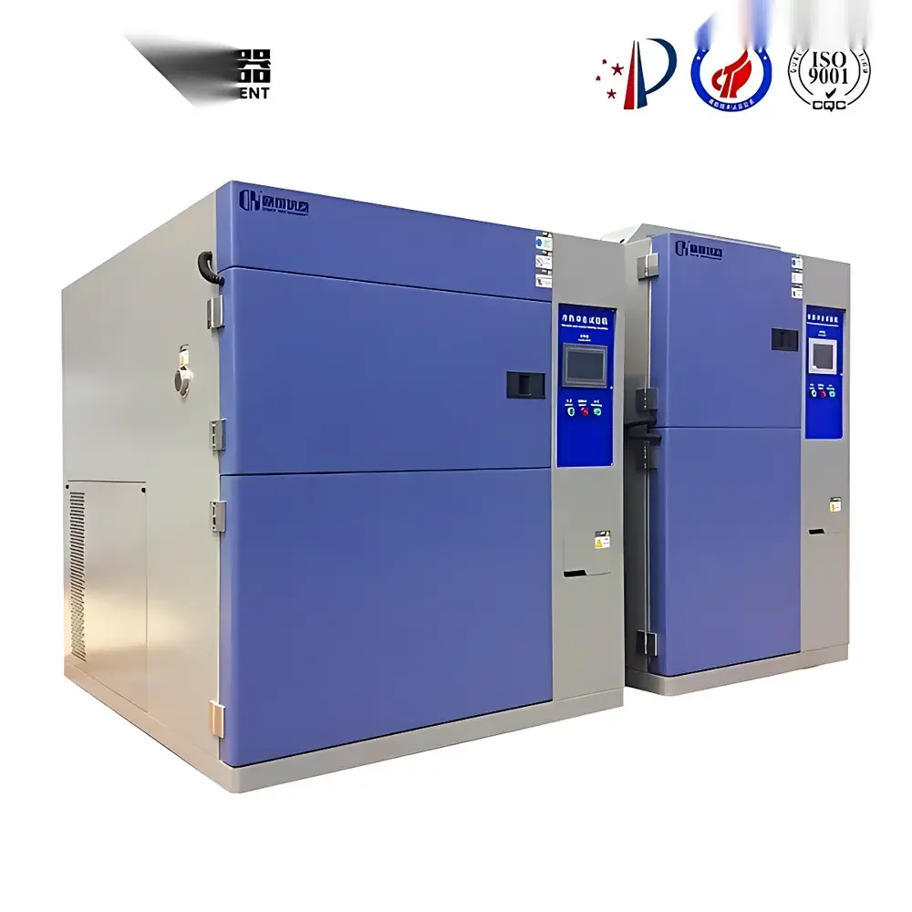
Thermal Shock Test Chamber – Dual-Chamber Rapid Temperature Cycling System
| Brand | OEM |
|---|---|
| Origin | Imported |
| Manufacturer Type | Authorized Distributor |
| Price | USD 11,200 (FOB) |
| Compliance | GB/T 2423.22-2002, IEC 60068-2-14, GJB 150.5-2009, MIL-STD-810H Method 503.5, QC/T 17-1992, EIA-364-32 |
Overview
The Thermal Shock Test Chamber – Dual-Chamber Rapid Temperature Cycling System is an engineered environmental stress screening (ESS) platform designed to evaluate material and component resilience under extreme, rapid thermal transitions. Operating on the principle of mechanical separation between high-temperature and low-temperature zones—typically maintained at +150 °C and −70 °C respectively—the system transfers test specimens pneumatically or via robotic shuttle between chambers in ≤10 seconds, achieving temperature transition rates exceeding 15 °C/s (measured at specimen surface). This architecture eliminates thermal lag inherent in single-chamber ramp-and-soak systems and enables precise replication of real-world thermal shock profiles encountered during aerospace deployment, automotive powertrain operation, or field deployment of embedded electronics. The chamber’s core function is not merely temperature exposure, but controlled acceleration of thermomechanical fatigue mechanisms—including interfacial delamination, solder joint cracking, coefficient-of-thermal-expansion (CTE) mismatch strain, and glass transition–induced embrittlement—thereby exposing latent design or process weaknesses prior to field failure.
Key Features
- Dual-chamber configuration with independent refrigeration circuits: high-temp zone (up to +150 °C) and low-temp zone (down to −70 °C), eliminating cross-contamination and enabling true step-change thermal profiling
- High-efficiency dual-stage cascade refrigeration system utilizing imported semi-hermetic compressors (Germany-sourced), integrated with water-cooled condensers requiring external cooling tower (10 m³/h capacity)
- Energy modulation control logic that dynamically adjusts refrigerant mass flow and heater output to maintain setpoint stability ±0.5 °C while minimizing compressor cycling and energy consumption
- Stainless-steel interior construction (AISI 304) with reinforced insulated doors, argon-filled double-glazed viewing window, and NIST-traceable Class I temperature sensors (Pt100, ±0.15 °C accuracy)
- Programmable controller supporting up to 999 cycles, 99 segments per cycle, with user-definable dwell time (1 s–999 h), transfer time (5–30 s), and thermal overshoot compensation algorithms
- Integrated safety architecture including over-temperature cut-off, refrigerant high-pressure shutdown, door interlock, and independent mechanical temperature limiter
Sample Compatibility & Compliance
This thermal shock chamber accommodates standard test specimens up to 500 mm × 500 mm × 500 mm (W×D×H) and supports mounting fixtures for PCB assemblies, semiconductor packages (QFP, BGA, CSP), automotive ECUs, battery modules, optical housings, and polymer encapsulants. It is fully compliant with international reliability testing standards including IEC 60068-2-14 (Test Nb: Change of temperature), MIL-STD-810H Method 503.5 (Temperature Shock), GJB 150.5-2009 (Military Standard for Environmental Testing), GB/T 2423.22-2002 (Environmental testing – Tests Nc: Change of temperature), and EIA-364-32 (Thermal shock testing of electrical connectors). All calibration procedures follow ISO/IEC 17025 requirements, and temperature uniformity (±2.0 °C) and stability (±0.5 °C) are verified per ASTM E74 and IEC 60068-3-5.
Software & Data Management
The chamber integrates with optional PC-based control software compliant with FDA 21 CFR Part 11 and EU Annex 11 requirements. Software features include real-time multi-channel temperature logging (10 Hz sampling), automated report generation (PDF/CSV), electronic signature capability, audit trail with immutable timestamped records, and role-based user access control (administrator, operator, reviewer). Data export supports direct integration into LIMS platforms and statistical process control (SPC) dashboards. All temperature profiles, cycle logs, alarm histories, and calibration certificates are stored with SHA-256 hash integrity verification for GLP/GMP traceability.
Applications
- Qualification testing of avionics components per DO-160 Section 4 (Temperature Variation)
- Solder joint reliability assessment for automotive ADAS modules under ISO 16750-4 thermal cycling conditions
- Material compatibility validation for conformal coatings and underfill epoxies in high-reliability electronics
- Process validation of reflow soldering and die-attach thermal profiles in semiconductor packaging lines
- Accelerated life testing of lithium-ion battery cells under dynamic thermal load (e.g., EV battery pack thermal management validation)
- Failure mode analysis (FMA) of MEMS devices subjected to repeated thermal expansion/contraction cycles
FAQ
What is the minimum achievable transfer time between chambers?
Standard pneumatic shuttle mechanism achieves ≤8 seconds; optional high-speed robotic arm reduces transfer to ≤5 seconds (requires extended chamber footprint).
Does the system support programmable ramp rates within each chamber?
No—this is a step-function thermal shock system. Ramp rates are intentionally eliminated to isolate pure thermal shock effects; for gradient-based thermal cycling, a separate temperature-humidity chamber is recommended.
Is remote monitoring and alarm notification supported?
Yes—via Ethernet/IP with Modbus TCP interface; optional SMS/email alerts triggered by critical alarms (e.g., temperature deviation >±3 °C, compressor fault, door open >60 s).
What maintenance intervals are recommended for the cascade refrigeration system?
Compressor oil analysis every 2,000 operating hours; refrigerant purity check and filter-drier replacement every 12 months; full system leak test and pressure vessel inspection per ASME BPVC Section VIII every 36 months.
Can the chamber be validated for IQ/OQ/PQ protocols?
Yes—factory-supplied validation documentation includes URS, DQ, IQ/OQ templates aligned with ISO 13485 and GMP Annex 15; PQ execution requires customer-defined acceptance criteria and third-party metrology support.


