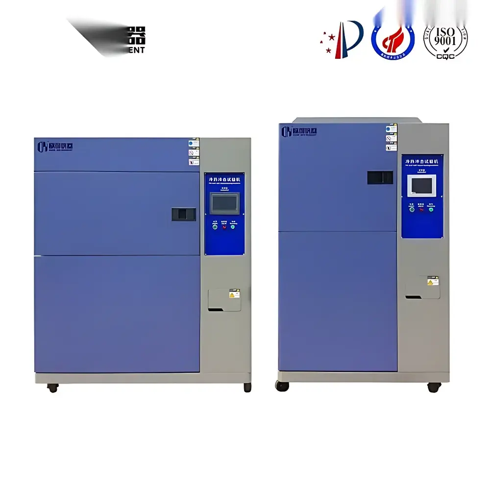
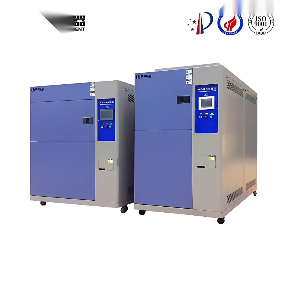
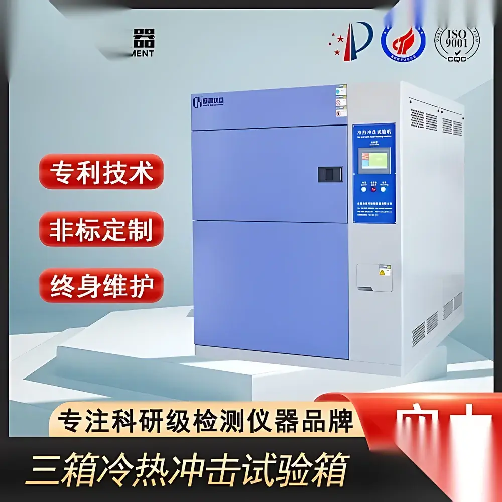
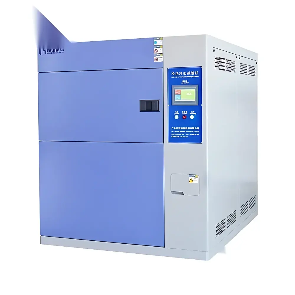
Thermal Shock Test Chamber – Dual-Chamber or Single-Chamber Configuration for Rapid Temperature Transition Testing
| Brand | OEM / Custom-Branded |
|---|---|
| Origin | Imported |
| Supplier Type | Authorized Distributor |
| Pricing | USD 11,200 (FOB) |
| Cooling System | Two-Stage Cascade Refrigeration with Imported Semi-Hermetic Compressor (Germany) |
| External Cooling Requirement | 10 m³/h Recirculating Cooling Tower (User-Supplied) |
| Compliance | IEC 60068-2-14 (Test N), MIL-STD-810G Method 503.5, GJB 150.5A-2009, GB/T 2423.22-2012, QC/T 17-1992, EIA-364-32 |
Overview
The Thermal Shock Test Chamber is an engineered environmental simulation system designed to evaluate material and component reliability under rapid, extreme temperature transitions. It operates on the principle of accelerated thermal stress induction—subjecting test specimens to abrupt shifts between high-temperature and low-temperature zones, thereby replicating real-world thermal cycling conditions encountered in aerospace, automotive, semiconductor, and defense applications. Unlike standard temperature-humidity chambers, this system implements either a dual-chamber (hot/cold separation) or single-chamber (air-baffle switching) architecture to achieve transition times as fast as 10–15 seconds between extremes (e.g., −65 °C to +150 °C), enabling precise quantification of thermo-mechanical fatigue, interfacial delamination, solder joint integrity, and coefficient-of-thermal-expansion (CTE)-induced microcracking. Its core function is not static conditioning but dynamic stress exposure—making it indispensable for HALT/HASS protocols, qualification testing per AEC-Q200, and failure mode analysis in high-reliability electronics.
Key Features
- Two-stage cascade refrigeration system utilizing imported semi-hermetic compressors (Germany), ensuring stable sub-zero operation down to −70 °C and rapid cooling ramp rates
- High-efficiency evaporative condenser interface enabling effective heat transfer between high- and low-temperature circuits
- Energy modulation control logic that dynamically adjusts refrigerant flow and compressor load—reducing power consumption by up to 28% during partial-load operation without compromising thermal stability
- Stainless-steel insulated chamber construction with multi-layer vacuum-insulated panels (VIPs) minimizing thermal leakage and improving temperature uniformity (±0.5 °C across work volume)
- Programmable transition timing, dwell duration, cycle count, and temperature setpoint sequencing via industrial-grade PLC controller with Ethernet/IP and Modbus TCP interfaces
- Integrated safety interlocks including over-temperature cutoff, refrigerant pressure monitoring, door-open alarm, and emergency stop with hardware-based fail-safe circuitry
Sample Compatibility & Compliance
The chamber accommodates test specimens ranging from bare die and BGA packages to full automotive ECUs and avionics enclosures (max. 500 kg loading capacity, customizable interior dimensions). It supports standardized mounting fixtures, thermocouple feedthroughs (Type K/T), and optional inert gas purge (N₂) for oxidation-sensitive samples. Regulatory alignment includes full traceability to IEC 60068-2-14 (Test N), MIL-STD-810G Method 503.5, GJB 150.5A-2009, and GB/T 2423.22-2012. Calibration documentation follows ISO/IEC 17025 guidelines, with optional NIST-traceable sensor validation. For regulated industries, the system architecture supports 21 CFR Part 11-compliant audit trails when integrated with validated data acquisition software.
Software & Data Management
Control and monitoring are executed via a Windows-based HMI with embedded real-time logging (sample rate ≥1 Hz per channel). The software enables automated test script generation, deviation alerts with email/SMS notification, and export of CSV/Excel-compatible datasets compliant with ASTM E29-23 rounding conventions. Optional add-ons include GLP/GMP-compliant electronic signatures, role-based user access control (admin/operator/auditor tiers), and integration with LIMS platforms via RESTful API. All thermal profiles are stored with metadata including operator ID, calibration status, chamber serial number, and environmental ambient logs—ensuring full reproducibility for internal audits or regulatory submissions.
Applications
- Qualification of IC packaging materials (EMC, mold compound, underfill) against popcorn cracking and wire bond lift
- Validation of solder joint reliability in automotive ADAS modules per AEC-Q200 Rev D
- Thermal fatigue assessment of ceramic substrates and thin-film resistors in power electronics
- Testing of polymer seals, gaskets, and composite airframe components under cyclic thermal strain
- Accelerated life modeling for battery module housings and thermal interface materials (TIMs)
- Support of DOE-driven design verification in early-stage product development (Phase 0–2)
FAQ
What is the typical temperature transition time between extremes?
Standard configurations achieve ≤15 seconds for −65 °C ↔ +150 °C transitions in dual-chamber mode; single-chamber variants range from 20–35 seconds depending on load mass and insulation configuration.
Is external cooling water mandatory?
Yes—operation requires a dedicated recirculating cooling tower delivering 10 m³/h at 32 °C inlet temperature. Chiller-integrated variants are available upon request.
Can the chamber be validated for GxP environments?
Yes—IQ/OQ/PQ protocols are provided, and the system meets requirements for FDA-regulated device testing when paired with validated software and calibrated sensors.
What maintenance intervals are recommended for the refrigeration system?
Compressor oil analysis every 2,000 operating hours; refrigerant purity checks annually; full system leak inspection and filter-drier replacement every 18 months.
Does the controller support custom test profiles beyond standard compliance methods?
Yes—the scripting engine accepts user-defined ramp/dwell sequences, conditional branching, and pass/fail logic based on real-time sensor feedback.


