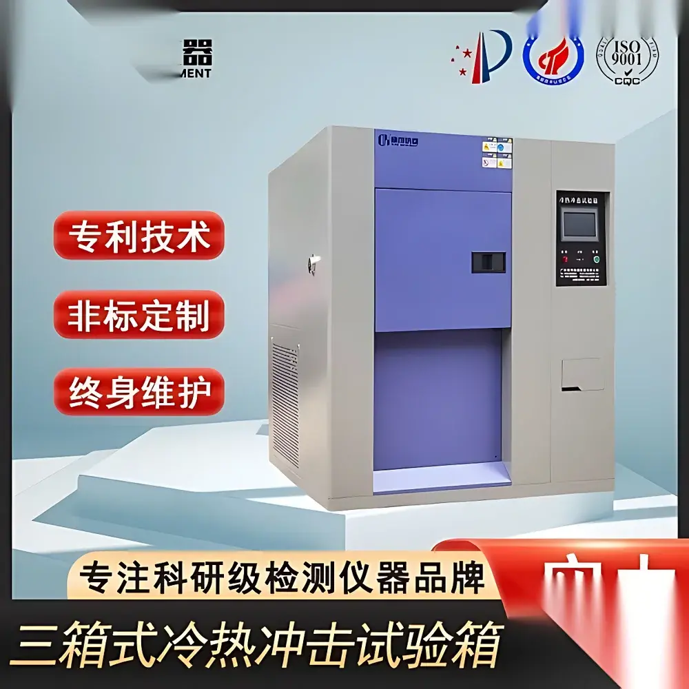
Thermal Shock Test Chamber – Industrial-Grade Dual- and Tri-Zone Environmental Test System
| Brand | Other Brands |
|---|---|
| Origin | Imported |
| Manufacturer Type | Authorized Distributor |
| Price | USD 11,200 (FOB) |
| Cooling Capacity | Dual-Stage Cascade Refrigeration System |
| Compressor | Imported Semi-Hermetic German Compressor |
| Cooling Water Requirement | 10 m³/h External Cooling Tower |
| Compliance | IEC 60068-2-14 (Test N), MIL-STD-810G Method 503.5, GB/T 2423.22-2002, GJB 150.5-2009, QC/T 17-1992, EIA-364-32 |
Overview
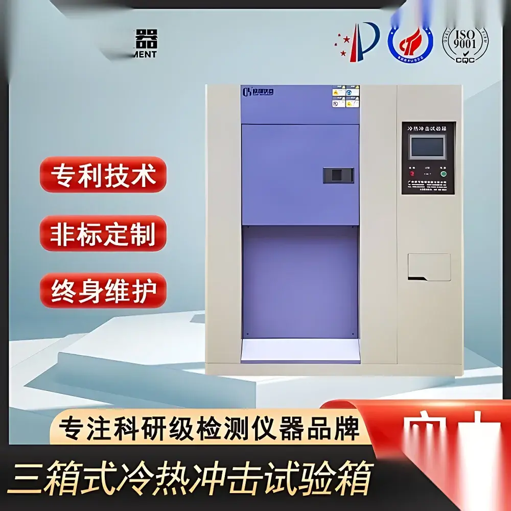
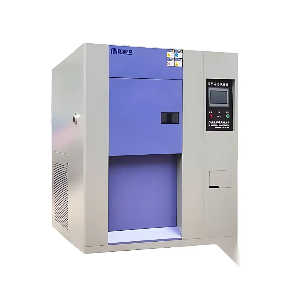
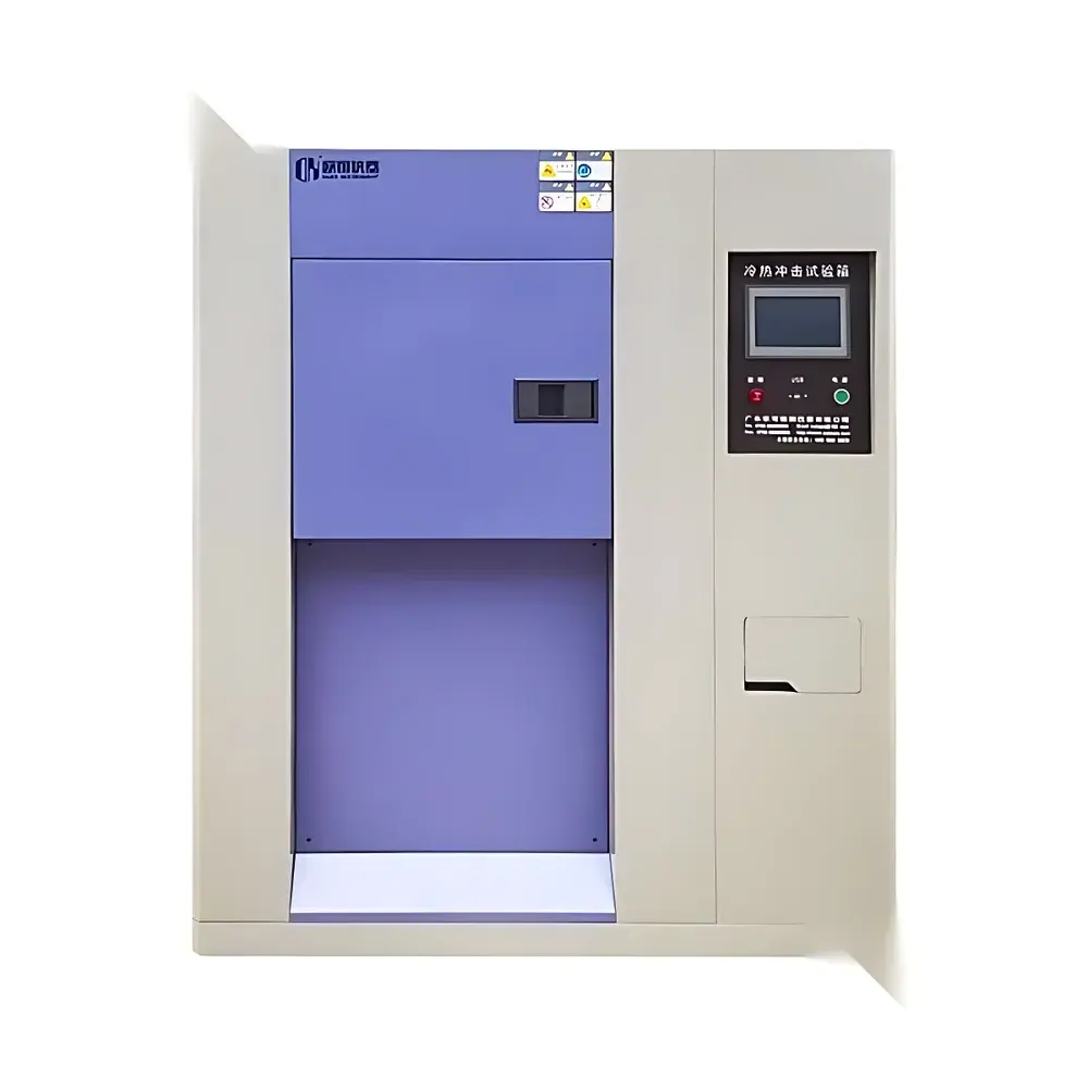
The Thermal Shock Test Chamber is an industrial-grade environmental test system engineered for rapid, repeatable, and highly controlled temperature transitions between extreme thermal conditions. It operates on the principle of accelerated thermal stress induction—subjecting electronic components, automotive modules, aerospace materials, and PCB assemblies to abrupt temperature shifts (e.g., −65 °C ↔ +150 °C) to evaluate material integrity, solder joint reliability, seal performance, and interfacial delamination resistance. Two structural configurations are available: dual-zone (hot/cold chambers with mechanical basket transfer) and tri-zone (separate hot soak, cold soak, and test chambers with static sample placement). Both designs comply with the fundamental thermodynamic constraints of thermal shock testing, ensuring minimal thermal inertia during transition and precise dwell time control per IEC 60068-2-14 Annex A.
Key Features
- Dual-configuration flexibility: Select between dual-chamber (basket-driven transfer) or tri-chamber (static test chamber) architecture based on throughput, specimen size, and test protocol requirements.
- Cascade refrigeration architecture: Utilizes a two-stage semi-hermetic German compressor system with R404A/R23 refrigerant pairing, enabling stable operation down to −70 °C and rapid recovery times (< 5 min from −65 °C to +150 °C).
- Energy-regulated cooling system: Integrated capacity modulation maintains consistent refrigerant mass flow across varying load conditions—reducing compressor cycling, extending service life, and improving long-term temperature stability (±0.3 °C in dwell phase).
- Robust chamber construction: Inner walls of SUS304 stainless steel; insulated with high-density polyurethane foam (≥150 mm thickness); door gasket sealed with magnetic silicone for leak-tight thermal isolation.
- Real-time thermal profiling: Equipped with calibrated PT100 sensors (traceable to NIST standards) at multiple chamber locations—including sample zone, air inlet, and evaporator outlet—for synchronized data logging and thermal uniformity validation.
Sample Compatibility & Compliance
The chamber accommodates specimens up to 500 × 500 × 500 mm (W×D×H) and supports weight loads up to 30 kg per test cycle. It is validated for use with printed circuit boards, semiconductor packages (QFP, BGA), battery cells, optical sensors, and polymer-based enclosures. All operational modes meet mandatory compliance requirements for qualification testing under MIL-STD-810G Method 503.5 (Temperature Shock), IEC 60068-2-14 (Test N), GJB 150.5-2009 (Chinese military standard for temperature impact), and EIA-364-32 (thermal cycling of connectors). The system supports GLP-compliant test execution when paired with audit-trail-enabled software—full traceability of setpoints, dwell durations, transition rates, and alarm events is retained for FDA 21 CFR Part 11–aligned environments.
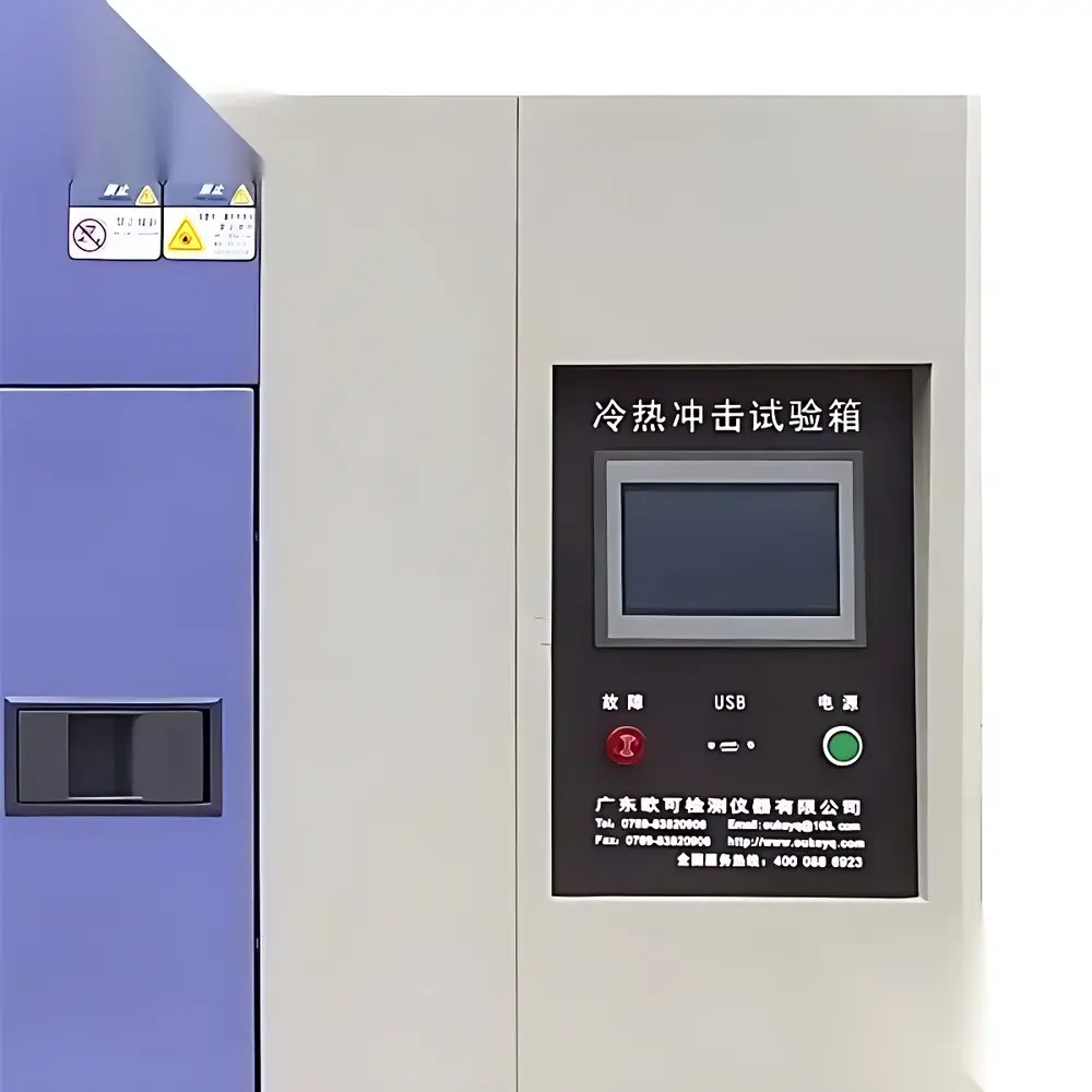
Software & Data Management
Control is managed via a 10.1″ capacitive touchscreen HMI running embedded Linux OS with deterministic real-time scheduling. The interface provides intuitive access to multi-step profile programming, manual override, and live thermal mapping visualization. Optional PC-based software (Windows/Linux compatible) enables remote monitoring, automated report generation (PDF/CSV), and integration with LIMS or MES platforms via Modbus TCP or OPC UA. All logged data—including chamber air temperature, sample surface temperature (via optional thermocouple inputs), compressor status, and door open/close timestamps—is time-stamped with microsecond precision and stored with SHA-256 checksum integrity verification. Audit trails record user login/logout, parameter changes, and calibration interventions—fully compliant with ISO/IEC 17025 documentation requirements.
Applications
- Reliability screening of automotive ECUs subjected to under-hood thermal transients per QC/T 17-1992.
- Qualification of avionics hardware against MIL-STD-810G thermal shock criteria prior to flight certification.
- Failure mode analysis of MEMS devices exposed to repeated −55 °C/+125 °C cycles.
- Process validation of conformal coating adhesion on flex-rigid PCBs under accelerated thermal fatigue.
- Material compatibility testing of elastomeric seals used in medical device housings per ISO 10993-12 environmental stress protocols.
FAQ
What is the difference between dual-zone and tri-zone thermal shock configurations?
Dual-zone systems use a movable basket to shuttle samples between hot and cold chambers—ideal for high-throughput production testing. Tri-zone systems maintain separate hot/cold storage zones and a static test chamber, minimizing thermal disturbance during dwell phases and offering superior temperature uniformity for R&D-grade validation.
Is external cooling water infrastructure mandatory?
Yes. The cascade refrigeration system requires a dedicated closed-loop cooling tower delivering 10 m³/h of water at ≤32 °C inlet temperature. This is non-negotiable for sustained operation below −60 °C and meets ASHRAE Guideline 15 safety thresholds for refrigerant charge management.
Can the chamber be integrated into an automated test cell?
Absolutely. Standard Modbus TCP and optional EtherCAT interfaces support synchronization with robotic loaders, power analyzers, and functional testers—enabling fully unattended thermal stress campaigns with pass/fail logic gating.
Does the system support custom ramp rate programming?
Yes. Transition rates between temperature extremes are programmable from 10 °C/min to 60 °C/min (typical), with independent control over heating and cooling acceleration profiles—critical for simulating real-world thermal gradients in engine bay or spacecraft thermal blankets.
How is calibration traceability maintained?
Each unit ships with a factory calibration certificate (NIST-traceable PT100 sensors), and the onboard calibration routine supports user-performed sensor verification using reference dry-block calibrators—fully documented per ISO/IEC 17025 Clause 6.5.


")