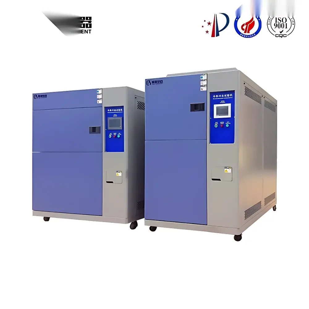
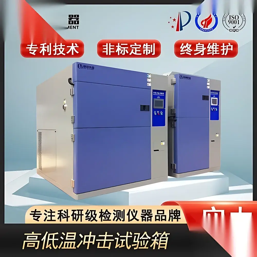
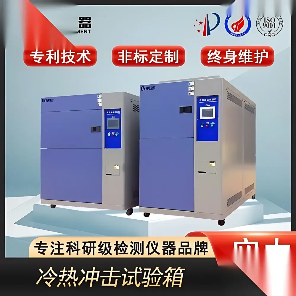
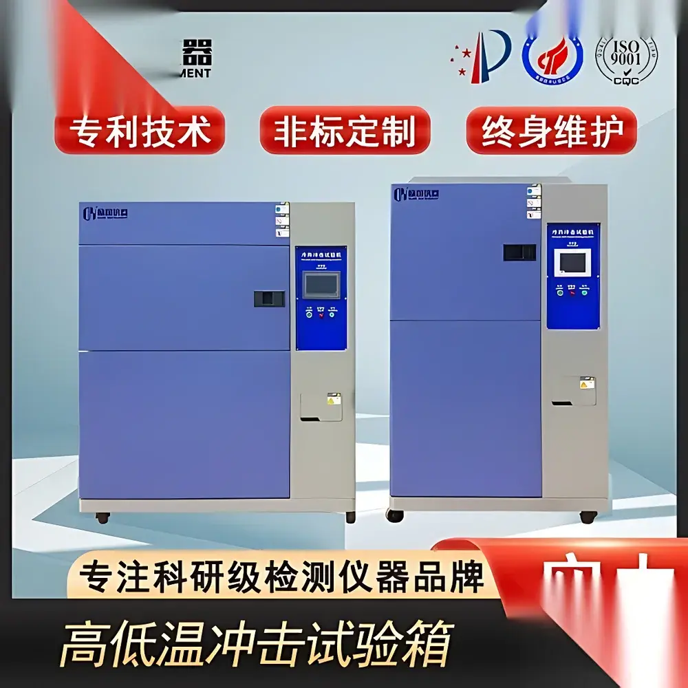
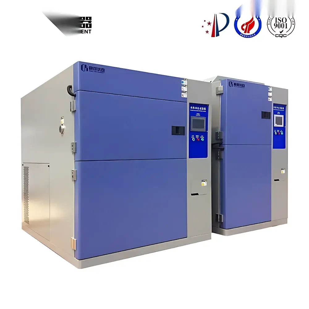
Thermal Shock Test Chamber – Standard Dual-Chamber Vertical Configuration
| Brand | OEM / Custom-Branded |
|---|---|
| Origin | Imported |
| Manufacturer Type | Authorized Distributor |
| Pricing | USD 11,200 (FOB) |
| Temperature Transition Time | ≤15 s |
| Temperature Recovery Time | ≤5 min |
| Control Resolution | ±0.1 °C |
| Refrigeration System | Twin-Circuit Cascade Design with Imported French Tecumseh Compressors |
| Construction | Stainless Steel Interior + Powder-Coated Steel Exterior |
| Cooling Medium | Eco-Friendly R404A/R23 Blend |
| Compliance | ISO 16750-4, JEDEC JESD22-A104, MIL-STD-810H Method 503.5, IEC 60068-2-14 |
Overview
The Thermal Shock Test Chamber – Standard Dual-Chamber Vertical Configuration is an engineered environmental simulation system designed to evaluate material and component reliability under rapid, extreme thermal transitions. Based on the vertical two-box method (IEC 60068-2-14 Clause 3), it physically separates high-temperature and low-temperature zones with a lift-type transfer mechanism, enabling precise, repeatable thermal shock profiles without cross-contamination of air streams. This architecture eliminates thermal lag associated with single-chamber ramp-and-soak methods and ensures true step-change exposure—critical for validating solder joint integrity, encapsulant adhesion, PCB warpage, and hermetic seal performance in automotive electronics, aerospace avionics, and semiconductor packaging.
Key Features
- Vertical dual-zone configuration with independent high-temperature (+150 °C max) and low-temperature (−70 °C min) chambers, isolated by motorized lift platform for specimen transfer
- Twin-circuit cascade refrigeration system utilizing imported French Tecumseh compressors; primary stage (R404A) and secondary stage (R23) optimized per operational temperature band to maximize efficiency and compressor service life
- High-precision PID controller with ±0.1 °C setpoint resolution, real-time monitoring, and programmable soak dwell times per zone
- Horizontal airflow distribution via centrifugal blower and optimized duct geometry—ensuring uniform temperature distribution (±0.5 °C within working volume per ISO 16750-4 Annex B)
- Stainless steel interior chamber (SUS304) with seamless welded corners and powder-coated structural frame; fully insulated with ≥150 mm thick polyurethane foam (thermal conductivity ≤0.022 W/m·K)
- Integrated safety architecture: over-temperature cut-off, compressor high-pressure/low-pressure switches, phase failure protection, door interlock, and automatic power disconnect upon fault detection
- LCD touch interface with multilingual GUI (English, German, Japanese), data logging capability (internal SD card + USB export), and configurable alarm thresholds
Sample Compatibility & Compliance
This chamber accommodates specimens up to 600 mm × 600 mm × 600 mm (W×D×H) and supports standardized test protocols including JEDEC JESD22-A104 (Temperature Cycling), MIL-STD-810H Method 503.5 (Temperature Shock), and ISO 16750-4 (Road Vehicles – Environmental Conditions). Its mechanical design conforms to GLP-compliant installation requirements: vibration-isolated mounting, dedicated grounding, and ambient cooling water supply specification (15–30 °C, 2–4 bar, flow rate ≥3 L/min). All electrical components meet CE marking directives (2014/30/EU EMC, 2014/35/EU LVD), and refrigerant selection complies with EU F-Gas Regulation (No. 517/2014) and EPA SNAP Program guidelines.
Software & Data Management
The embedded controller logs timestamped temperature readings from dual PT100 sensors (one per chamber) at user-defined intervals (1–60 s). Exported CSV files include chamber ID, setpoint, actual value, deviation, alarm status, and cycle counter—structured for direct import into statistical process control (SPC) platforms such as Minitab or JMP. Optional Ethernet/IP interface enables remote monitoring via Modbus TCP or OPC UA, supporting integration into centralized lab management systems compliant with FDA 21 CFR Part 11 (audit trail, electronic signature, and role-based access control available with optional software license).
Applications
- Qualification testing of automotive ECUs per ISO 16750-4 Level 3 (−40 °C ↔ +105 °C, 1000 cycles)
- Solder fatigue analysis in surface-mount assemblies using JEDEC-defined profiles (e.g., −55 °C ↔ +125 °C, ΔT ≥100 K)
- Validation of optical sensor housings exposed to desert-to-mountain thermal gradients
- Reliability screening of medical device PCBs prior to ISO 13485-certified production release
- Material coefficient-of-thermal-expansion (CTE) mismatch evaluation in multi-layer ceramic capacitors (MLCCs)
FAQ
What is the difference between vertical two-box and horizontal three-box thermal shock configurations?
The vertical two-box design minimizes footprint and eliminates horizontal transfer rail contamination risk; it achieves faster transition times (≤15 s) due to shorter travel distance and higher acceleration. Horizontal three-box systems offer greater payload flexibility but require longer stabilization after transfer.
Can this chamber perform ramp-and-soak profiles in addition to thermal shock?
Yes—the controller supports programmable temperature ramps (0.1–10 °C/min), dwell periods, and cycling sequences, enabling combined environmental stress screening (ESS) protocols per IPC-9701.
Is calibration traceable to NIST or equivalent national standards?
Factory calibration uses ISO/IEC 17025-accredited reference probes; users receive a certificate of calibration with uncertainty values referenced to NIST-traceable standards.
What maintenance intervals are recommended for the refrigeration system?
Compressor oil analysis every 2,000 operating hours; condenser coil cleaning quarterly; refrigerant leak check semiannually per ASHRAE Guideline 3-2021.
Does the system support custom test script execution via external PC?
Yes—via RS-485 or Ethernet, third-party software (LabVIEW, Python pySerial) can send SCPI-like commands for full sequence automation and synchronized data acquisition with external DAQ systems.


