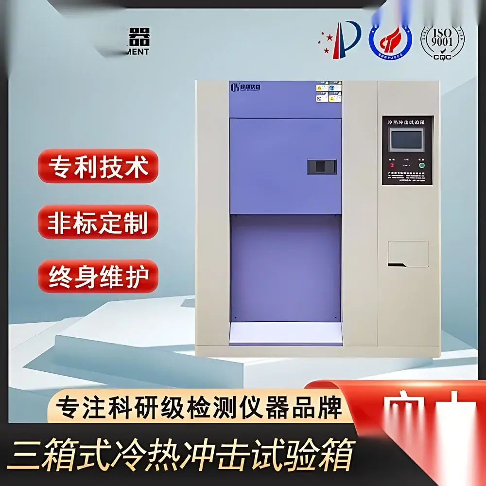
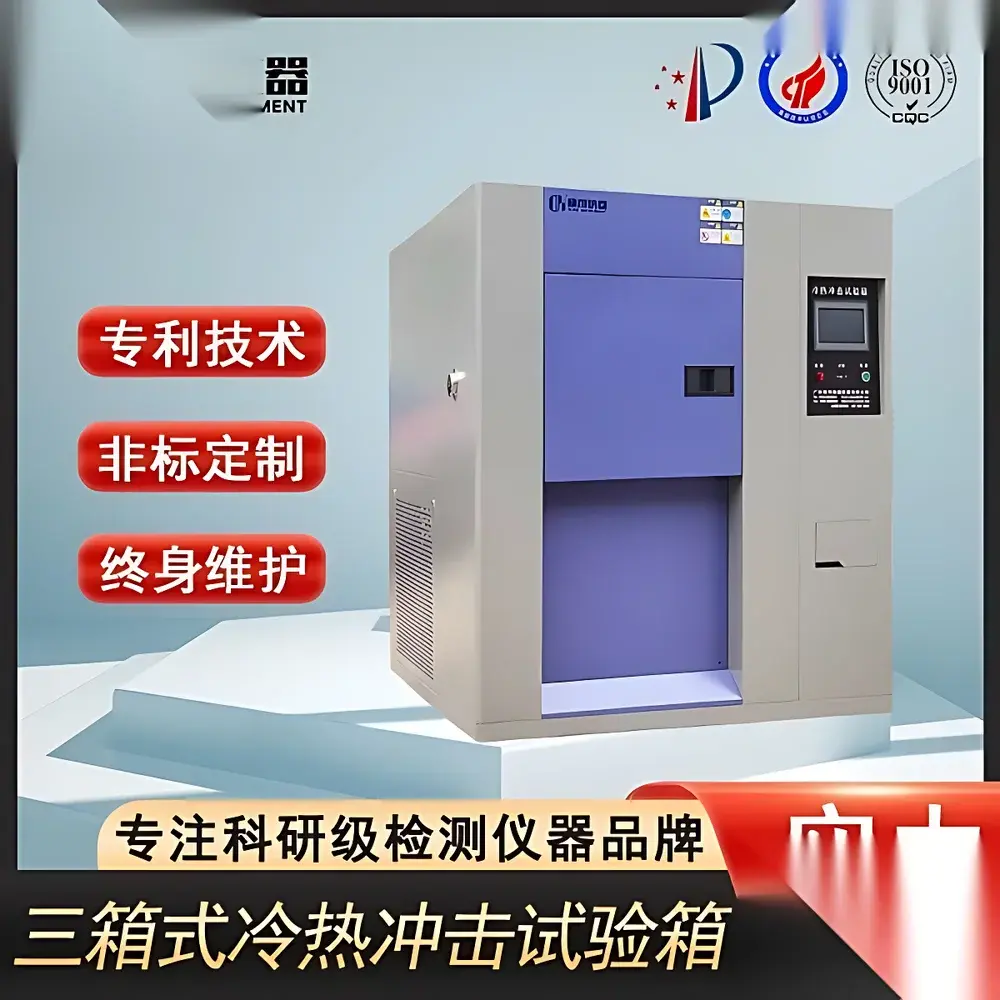
Thermal Shock Test Chamber – Standard Dual-Zone Rapid Transition Environmental Test System
| Brand | OEM / Generic |
|---|---|
| Origin | Imported |
| Distributor Type | Authorized Reseller |
| Price | USD 11,200 (FOB) |
| Temperature Range | -65°C to +180°C |
| Transition Time (Hot ↔ Cold) | ≤15 s |
| Temperature Recovery Time | ≤5 min |
| Control Resolution | ±0.1°C (Temp), ±1 s (Time) |
| Programmable Memory | 10 programs × 99 segments |
| Power Supply | AC 380 V ±10%, 50 Hz ±1 Hz, 3-phase 4-wire |
| Ambient Operating Conditions | 5–30°C, ≤85% RH |
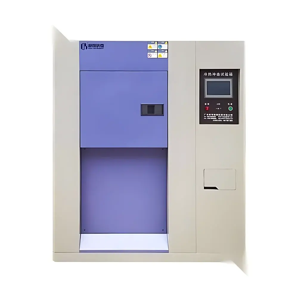
| Construction | Outer Shell – Brushed SUS304 Stainless Steel |
| Standard Accessories | Multi-layer Heated Defrost Viewing Window, 2 Adjustable Sample Racks, 1 × Ø50 mm Cable Port |
| Safety Protections | Independent Over-Temperature Cut-off, Compressor High-Pressure & Overload Protection, Motor Thermal Overload, Phase Failure/Reverse Phase Detection, Dry-Run Prevention for Heating Elements |
Overview
The Thermal Shock Test Chamber – Standard Dual-Zone Rapid Transition Environmental Test System is an engineered solution for accelerated reliability assessment under extreme thermal cycling conditions. Designed in accordance with the fundamental principles of dual-chamber thermal shock testing—where specimens are rapidly transferred between independently controlled high-temperature and low-temperature zones—the system enables precise simulation of real-world thermal stress events encountered during product lifecycle operation. Unlike single-chamber ramp-based systems, this configuration eliminates thermal inertia limitations, delivering true step-change temperature exposure essential for evaluating solder joint integrity, polymer dimensional stability, coating adhesion, and interfacial delamination in electronic assemblies, automotive ECUs, aerospace composites, and medical device housings. The chamber meets core functional requirements aligned with ASTM D5229/D5229M (low-temperature impact), IEC 60068-2-14 (Test Nb: Change of temperature), and MIL-STD-810H Method 503.7 (Temperature Shock), serving as a foundational tool for qualification testing in R&D labs, quality assurance departments, and third-party certification facilities.
Key Features
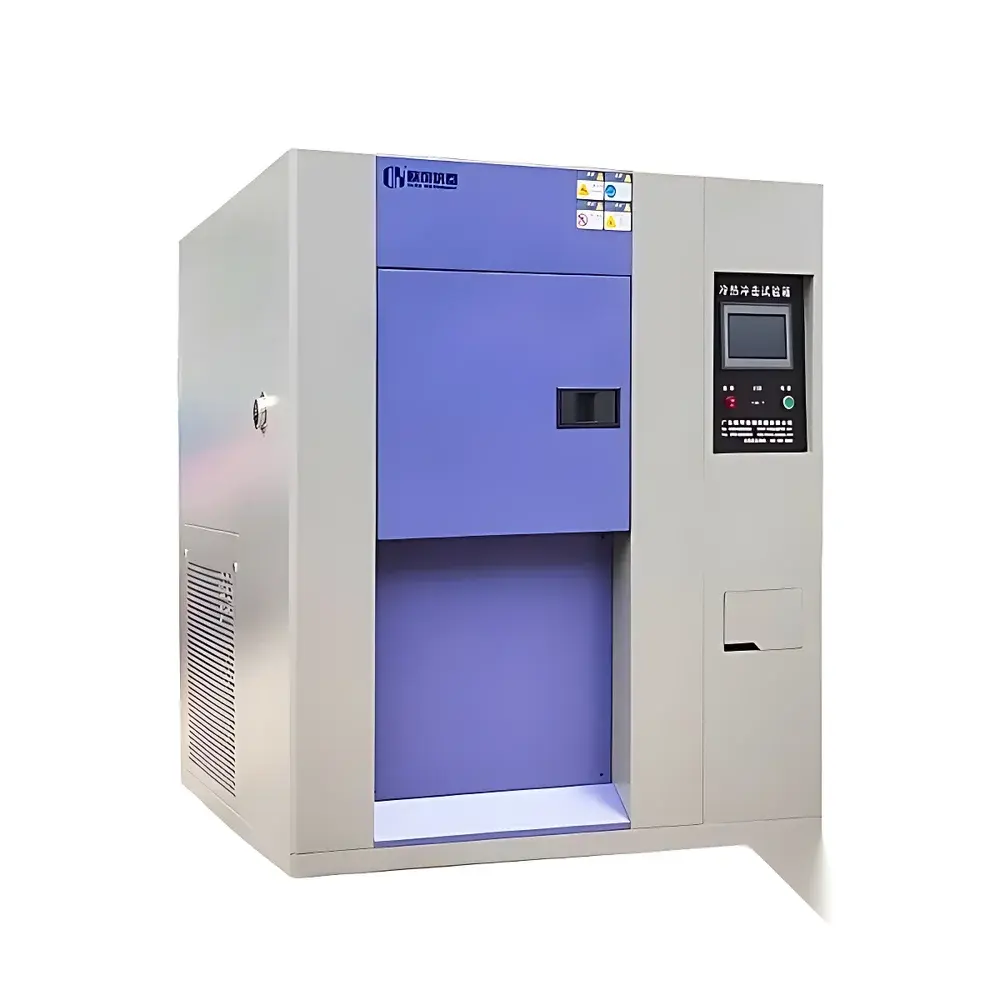
- Dual-zone architecture with physically isolated hot and cold chambers, enabling independent temperature control from –65°C to +180°C with minimal cross-contamination
- High-speed pneumatic transfer mechanism achieving specimen transition in ≤15 seconds—meeting stringent IEC 60068-2-14 Class 1 timing criteria
- Liquid nitrogen or mechanical cascade refrigeration options available; heating via stainless steel finned tubular heaters with PID-controlled power modulation
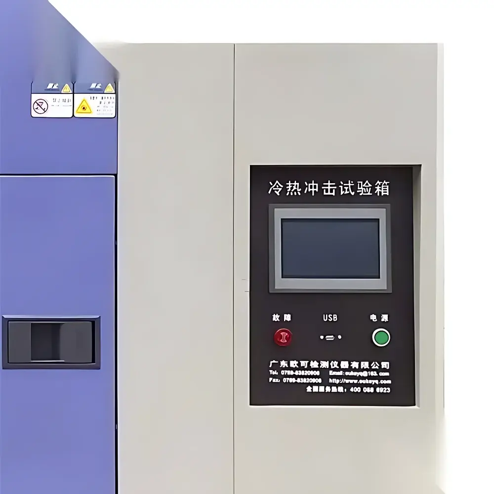
- Intelligent touchscreen controller featuring real-time graphical display of setpoints, actual chamber temperatures, elapsed cycle time, and heater/compressor status
- Auto-tuning PID algorithm with adaptive learning for stable regulation across wide dynamic ranges; supports both programmable ramp-soak profiles and fixed-point dwell testing
- Integrated fault diagnostics with on-screen error codes, event logging, and audible/visual alarms for over-temperature, compressor overload, phase loss, and sensor failure
- RS-485 interface compliant with Modbus RTU protocol; optional Ethernet module supports remote monitoring and data export via standard OPC UA or FTP protocols
- Robust mechanical construction: brushed SUS304 outer enclosure, mirror-finish SUS304 interior, 150 mm thick composite insulation (polyurethane foam + glass fiber), and dual-lip silicone gaskets rated for –70°C to +200°C service
Sample Compatibility & Compliance
This thermal shock chamber accommodates test specimens up to 500 mm × 500 mm × 500 mm (W×D×H) on two adjustable stainless steel racks. A standardized Ø50 mm cable port with silicone plug allows for real-time electrical signal monitoring during cycling. The viewing window incorporates multi-layer heated glass with anti-fog coating, enabling visual inspection without interrupting test continuity. All operational parameters—including temperature setpoints, dwell durations, transition triggers, and alarm thresholds—are fully configurable to align with internal test specifications or external standards such as ISO 16750-4 (road vehicles), JEDEC JESD22-A104 (integrated circuits), and AEC-Q200 (passive components). Audit-ready data logs include timestamps, operator ID (via optional login), parameter versions, and calibration traceability metadata—supporting GLP/GMP documentation workflows and FDA 21 CFR Part 11 compliance when paired with validated software packages.
Software & Data Management
Bundled PC-based software provides comprehensive test orchestration, including drag-and-drop program building, real-time multi-channel trend visualization, and automated report generation in PDF/CSV formats. Each test run generates a digitally signed audit trail containing controller firmware version, calibration certificate expiry dates, environmental ambient readings, and user-defined annotations. Raw data files retain native resolution (0.1°C, 1 s) and support post-processing in MATLAB, Python (Pandas), or JMP. Optional cloud synchronization enables centralized fleet monitoring across geographically dispersed laboratories, with role-based access control and encrypted TLS 1.2 transmission. Firmware updates are delivered via secure HTTPS channels with SHA-256 signature verification to ensure system integrity.
Applications
- Electronics: Solder joint fatigue analysis in PCBAs, die attach reliability in power modules, wire bond lift-off evaluation in LED packages
- Automotive: ECU housing cracking validation, battery pack thermal interface material (TIM) performance under repeated expansion/contraction
- Aerospace: Composite laminate interlaminar shear strength degradation after thermal cycling, sealant durability in avionics enclosures
- Medical Devices: Sterilization-resistant polymer housing integrity, sensor housing hermeticity verification post-cycling
- Coatings & Adhesives: Cross-link density assessment via Tg shift measurement before/after shock exposure, intercoat adhesion loss quantification
- Research Institutions: Accelerated aging modeling for predictive lifetime estimation using Coffin-Manson or Norris-Landzberg empirical correlations
FAQ
What is the typical calibration interval recommended for this chamber?
Annual calibration against NIST-traceable reference thermometers is recommended; full system verification (including transfer timing and recovery rate) should be performed quarterly per ISO/IEC 17025 guidelines.
Can the chamber be integrated into an existing MES or LIMS environment?
Yes—via RS-485 Modbus RTU or optional Ethernet/IP interface, supporting bi-directional communication for job dispatch, status polling, and result ingestion using standard industrial protocols.
Is nitrogen purging capability available as an option?
Yes—optional LN2 purge manifold with mass flow controller and O₂ sensor enables inert atmosphere testing for moisture-sensitive or oxidation-prone materials.
Does the system support custom fixture mounting inside the test chamber?
The interior features standardized T-slot rails on all vertical walls and the floor, allowing secure attachment of customer-designed thermal mass fixtures or DUT-specific carriers.
How is traceability maintained for critical test parameters?
All controller firmware, calibration certificates, and software versions are embedded in exported data files; digital signatures prevent tampering, satisfying ALCOA+ (Attributable, Legible, Contemporaneous, Original, Accurate, Complete, Consistent, Enduring, Available) data integrity requirements.


")
