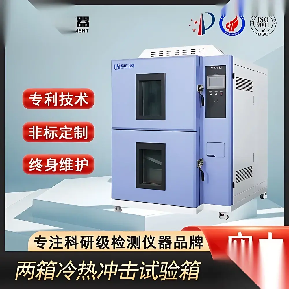
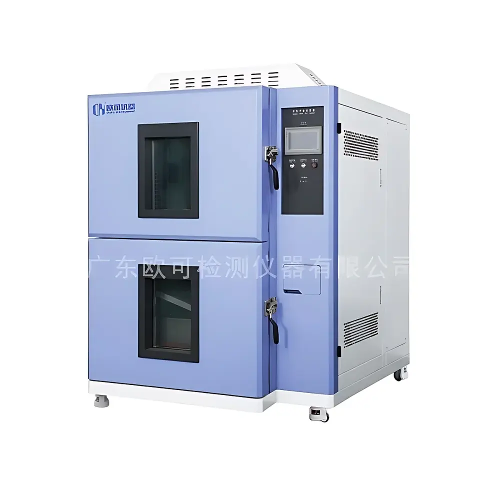
Thermal Shock Test Chamber – Three-Zone Rapid Temperature Transition Chamber with BTC Control Architecture
| Brand | OEM / Custom Brand |
|---|---|
| Origin | Imported |
| Manufacturer Type | Authorized Distributor |
| Pricing | USD 11,200 (FOB) |
| Temperature Range | -70°C to +180°C |
| Transition Time (Typ.) | ≤15 s (5℃ to -40℃ or +100℃ to -10℃, test zone) |
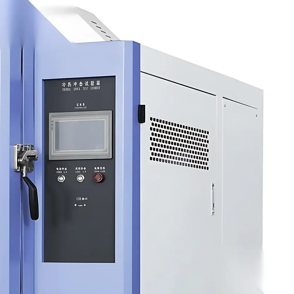
| Control System | TEMI880 Programmable Touchscreen Controller (Korean Origin) |
| Compliance Standards | GB 10589, GB 11158, GB 10586, IEC 60068-2-14, MIL-STD-810H Method 503.5 |
Overview
The Thermal Shock Test Chamber is an engineered environmental simulation system designed for accelerated reliability assessment of electronic components, aerospace materials, automotive ECUs, PCB assemblies, and optoelectronic devices under extreme thermal transients. It operates on a three-zone architecture—comprising independent high-temperature, low-temperature, and test chambers—enabling rapid, repeatable thermal shock cycles without mechanical movement of the test specimen. The chamber employs Balanced Temperature Control (BTC) methodology: a closed-loop proportional-integral-derivative (PID) algorithm dynamically modulates heating power and refrigerant flow to maintain setpoint stability within ±0.3°C during dwell phases, while minimizing overshoot during transitions. Unlike single-chamber cyclic systems, this design eliminates thermal inertia-related delays and ensures true step-change exposure per IEC 60068-2-14 Clause 6.2. The system supports both two-zone (hot ↔ cold) and three-zone (hot ↔ ambient ↔ cold) shock profiles, making it suitable for qualification testing per MIL-STD-810H Method 503.5 and JEDEC JESD22-A104F.
Key Features
- Three-zone segregated structure: independent hot zone (up to +180°C), cold zone (down to −70°C), and stationary test zone—ensuring zero sample displacement during shock transitions
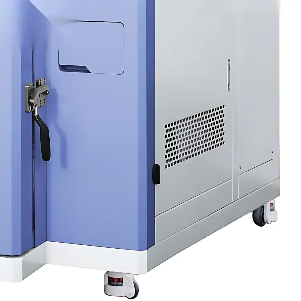
- BTC (Balanced Temperature Control) architecture with dual-stage refrigeration: primary R404A/R23 cascade system coupled with plate-type heat exchangers for stable thermal equilibrium and rapid recovery
- TEMI880 programmable controller (Korean origin): 7-inch full-color LCD touchscreen interface with multi-segment ramp-soak programming, cycle counting, auto-defrost scheduling, and real-time trend logging
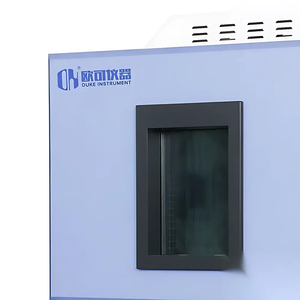
- Stainless steel 304 inner chamber with electrostatically applied powder-coated carbon steel outer enclosure; integrated observation window with anti-fog heated glass and LED interior lighting
- RS-232/RS-485 serial communication ports compliant with Modbus RTU protocol—enabling integration into centralized lab management systems or SCADA networks
- Pre-conditioning function: automatic pre-cooling/pre-heating prior to scheduled test initiation, reducing total test cycle time by up to 22% in multi-batch validation protocols
- Test port provision (Φ50 mm, sealed with silicone gasket): allows external power/signal cabling for in-situ functional monitoring during thermal stress
Sample Compatibility & Compliance
The chamber accommodates standard test specimens up to 500 mm × 500 mm × 500 mm (W×D×H) with maximum mass loading of 35 kg. Internal airflow is optimized via adjustable vane diffusers to ensure uniform temperature distribution (±1.5°C across test volume per IEC 60068-3-5). All structural materials meet RoHS Directive 2011/65/EU and REACH Annex XVII requirements. Calibration traceability follows ISO/IEC 17025:2017 via third-party accredited providers. The system supports audit-ready documentation for GLP and GMP environments, including electronic signature-capable operation logs, alarm history with timestamps, and deviation reporting aligned with FDA 21 CFR Part 11 Annex 11 principles.
Software & Data Management
The TEMI880 controller stores up to 100 user-defined test programs with 99 segments each, supporting complex profiles including dwell, ramp, and conditional branching (e.g., “if T ≥ 120°C for 15 min, initiate cold transfer”). Data export is available in CSV format via USB memory stick or direct serial transmission. Optional PC-based software (ChamberLink Pro v3.2) provides remote supervision, real-time graphing, statistical process control (SPC) charting, and automated report generation compliant with ASTM E2928-21 annexes. All data records include operator ID, environmental ambient logs, and refrigeration subsystem status flags—facilitating root-cause analysis during failure investigations.
Applications
This chamber is routinely deployed in: accelerated life testing of solder joints per IPC-9701; thermal fatigue evaluation of MEMS packaging; validation of conformal coating integrity under condensation-prone thermal cycling; qualification of battery module thermal interface materials (TIMs); and screening of optical lens adhesives for delamination resistance. Its ability to replicate field-relevant thermal gradients—such as those experienced during aircraft ascent/descent or automotive engine bay thermal transients—makes it indispensable for AEC-Q200-compliant component verification and ISO 16750-4 environmental stress screening.
FAQ
What is the minimum dwell time required between thermal transitions?
Standard configuration supports dwell times as short as 1 minute; extended dwell capability (up to 999 hours) is programmable per segment.
Does the system support automated defrost cycles during prolonged testing?
Yes—defrost frequency and duration are fully configurable; manual override is available via controller menu.
Can the chamber operate as a standalone high-temperature or low-temperature chamber?
Yes—the hot and cold zones may be decoupled to function independently as static ovens or freezers, maintaining ±0.5°C stability at setpoints.
Is NIST-traceable calibration documentation provided with shipment?
A factory calibration certificate (per ISO/IEC 17025) is included; on-site verification services are available upon request.
What ambient conditions are required for installation?
Ambient temperature: 5–28°C (24-hr average ≤28°C); relative humidity ≤85% RH; minimum clearance: 80 cm on all sides for ventilation and service access.


