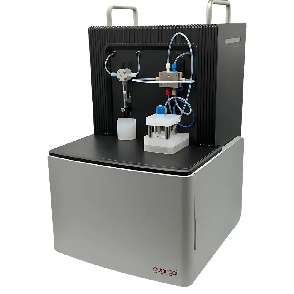
Toho SB1000 Seebeck Effect Measurement System
| Brand | Toho |
|---|---|
| Origin | Japan |
| Model | SB1000 |
| Temperature Range | 80 K – 700 K |
| Measurement Principle | Differential Thermoelectric Voltage Detection |
| Probe Configuration | 2-probe and 4-probe options |
| Sample Environment | High-vacuum compatible (integrated vacuum chamber) |
| Controller Type | Digital, microprocessor-based Seebeck coefficient controller |
| Cooling Method | Liquid nitrogen cryostat (for low-T) or heated stage (for high-T) |
| Data Acquisition | Real-time transient thermovoltage sampling with statistical averaging |
| Software Interface | PC-based control and analysis (Windows OS) |
Overview
The Toho SB1000 Seebeck Effect Measurement System is a precision-engineered platform for quantitative thermoelectric characterization of semiconductor and functional materials. It operates on the fundamental principle of the Seebeck effect—measuring the thermoelectric voltage (ΔV) generated across a material subjected to a controlled, spatially defined temperature gradient (ΔT)—to determine the Seebeck coefficient (S = −ΔV/ΔT) as a function of absolute temperature. Designed specifically for research and development laboratories engaged in thermoelectric materials science, the SB1000 integrates a digital controller with high-stability thermal management, enabling reproducible S(T) measurements across an extended operational range from 80 K to 700 K. Its architecture supports both cryogenic (liquid nitrogen-cooled) and resistively heated stages, and all thermal and electrical components are housed within a vacuum-compatible enclosure to eliminate convective heat loss and ambient oxidation—critical for air-sensitive semiconductors, chalcogenides, skutterudites, and half-Heuslers.
Key Features
- Digital microprocessor-controlled measurement engine with real-time feedback loop for ΔT stabilization and thermovoltage acquisition
- Differential voltage detection circuitry optimized for sub-μV resolution, delivering high signal-to-noise ratio even at low temperature gradients (≤ 1 K)
- Programmable temperature ramping and isothermal hold modes, synchronized with thermoelectric data capture
- Modular thermal stage support: interchangeable polyimide film heater stage (80–400 K) and high-temperature ceramic stage (200–700 K)
- Integrated dual-mode probe interface supporting both 2-probe (Seebeck-only) and 4-probe (simultaneous Seebeck + electrical resistivity) configurations
- Onboard statistical analysis engine performing real-time averaging, standard deviation calculation, and outlier rejection during transient thermovoltage sweeps
- Vacuum-tight mechanical design compatible with standard turbomolecular pumping systems (base pressure <1×10⁻⁵ mbar typical)
Sample Compatibility & Compliance
The SB1000 accommodates bulk polycrystalline pellets, sintered ceramics, single crystals, and thin-film samples (with appropriate mounting fixtures). Sample geometry requirements follow ASTM E1577–22 guidelines for thermoelectric property measurement: minimum length-to-width ratio of 3:1, surface flatness ≤ ±1 µm, and electrical contact resistance <10 mΩ per junction (verified via 4-point probe pre-test). The system’s vacuum-integrated configuration ensures compliance with ISO/IEC 17025–2017 requirements for controlled environmental testing conditions. When operated with calibrated reference standards (e.g., NIST SRM 3451), measurement uncertainty for S(T) is traceable to SI units under GLP-compliant documentation protocols. Full audit trail functionality—including operator ID, timestamped parameter logs, and raw thermovoltage waveform exports—is supported for FDA 21 CFR Part 11–aligned quality systems.
Software & Data Management
Control and analysis are performed via dedicated Windows-based software (SB1000 Control Suite v3.x), which provides intuitive workflow navigation, scriptable measurement sequences, and export-ready data formatting (CSV, HDF5, and MATLAB .mat). The software implements a differential algorithm that subtracts parasitic thermal EMFs from thermocouple junctions and wiring, significantly improving baseline stability. All acquired thermovoltage transients are time-stamped and tagged with concurrent temperature readings from dual Pt-100 sensors (±0.1 K accuracy). Raw and processed datasets include metadata headers compliant with MIAME and FAIR data principles. Optional API integration enables synchronization with third-party platforms such as LabVIEW or Python-based analysis pipelines (via TCP/IP socket interface).
Applications
- Thermoelectric figure-of-merit (zT) mapping of novel p-type and n-type semiconductor compounds
- Charge carrier type and effective mass estimation via S(T) sign and curvature analysis
- Validation of band structure models (e.g., single parabolic band vs. multi-band transport)
- Phase transition detection in correlated electron systems through anomalies in S(T) slope
- Stability assessment of thin-film thermoelectrics under thermal cycling (50–500 K, >100 cycles)
- Interfacial thermoelectric effects at heterojunctions and grain boundaries in polycrystalline devices
FAQ
What temperature calibration standards are supported by the SB1000?
The system accepts user-loaded calibration tables conforming to ITS-90; factory calibration uses NIST-traceable Pt-100 sensors and certified reference materials (e.g., Bi₂Te₃, PbTe) for S(T) verification.
Can the SB1000 measure thermal conductivity simultaneously?
No—the SB1000 is dedicated to Seebeck coefficient and electrical resistivity. For full zT determination, it is designed to interface with complementary instruments such as laser flash analyzers (LFA) or steady-state thermal conductivity modules.
Is remote operation possible?
Yes—Ethernet-enabled control allows secure remote access via VPN; full measurement scripting and live data streaming are supported without local GUI dependency.
What sample preparation guidelines apply for optimal 4-probe resistivity + Seebeck co-measurement?
Samples must feature four linearly aligned, low-resistance ohmic contacts (e.g., Au sputtered pads); inter-contact spacing should exceed 3× sample thickness to minimize current spreading errors per ASTM D4496.