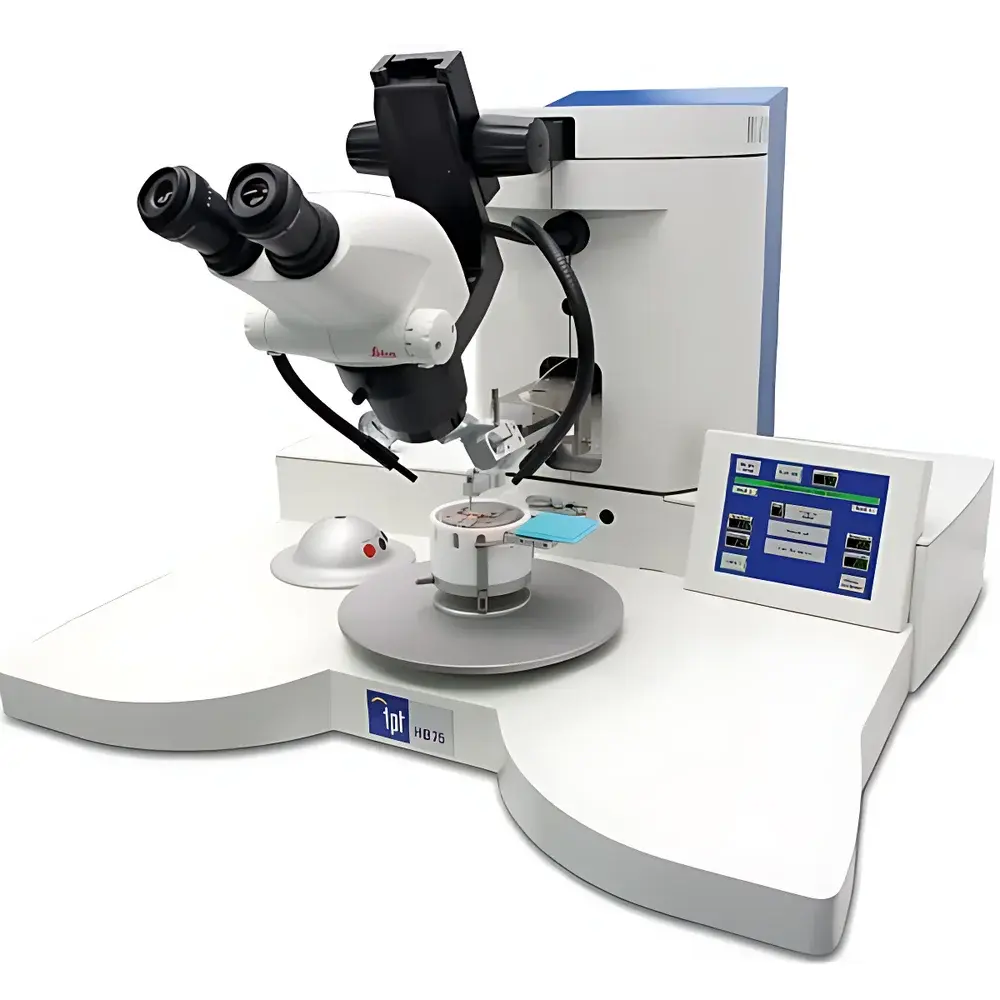
TPT HB75 Semi-Automatic Pick-and-Place Machine
| Brand | TPT |
|---|---|
| Origin | Germany |
| Model | HB75 |
| Mounting Type | Desktop |
| Control Interface | 6.5" TFT Touchscreen |
| Placement Accuracy | ±2 µm (typical, under calibrated lab conditions) |
| Chip Size Range | 100 µm × 100 µm to 10 mm × 10 mm |
| Z-Axis Stroke | 17 mm (motorized) |
| Placement Force Range | 10–150 cN·m (350 cN·m optional) |
| Placement Time | 1–10,000 ms (extendable to 20,000 ms) |
| Dispensing Capability | Optional adhesive dispensing module |
| Dip-Coating Function | Integrated |
| Vacuum Source | Onboard integrated vacuum pump |
| Motion Architecture | True orthogonal X-Y-Z kinematics |
| Tool Changer | Rotating nozzle turret |
| Programmable Recipes | Up to 100 stored programs |
| Operating Modes | Manual, semi-automatic, and step-by-step guided placement |
| Heating Stage | Optional temperature-controlled platform (up to 250 °C ±1 °C) |
| Power Supply | 100–240 V AC, ±10%, 50/60 Hz, max. 10 A |
| Dimensions (W×D×H) | 680 × 640 × 490 mm |
| Net Weight | 42 kg |
Overview
The TPT HB75 Semi-Automatic Pick-and-Place Machine is an engineered solution for high-precision die placement in low-volume, high-mix semiconductor assembly environments. Designed for laboratories, R&D centers, pilot lines, and niche production facilities, the HB75 implements a motorized Z-axis with true orthogonal motion control to ensure repeatable, traceable, and contamination-minimized handling of microcomponents. Its core architecture follows the principles of precision mechatronics—combining stepper-driven linear stages, vacuum-based pick-up, and programmable force-controlled placement—to meet the mechanical and thermal requirements of MEMS, MOEMS, optoelectronic subassemblies, and medical microdevices. Unlike fully automated systems requiring extensive integration, the HB75 delivers laboratory-grade placement fidelity without demanding factory-floor infrastructure or complex MES linkage.
Key Features
- Motorized Z-axis with 17 mm stroke and closed-loop position feedback for consistent placement force delivery (10–150 cN·m standard; 350 cN·m optional)
- True orthogonal X-Y manipulator (10 mm range, 6:1 mechanical advantage) enabling fine positional adjustment without parasitic coupling
- Integrated vacuum pump eliminating external hose routing and pressure instability
- Rotating nozzle turret supporting rapid tool change between suction nozzles (standard Ø1.58 mm, 19 mm length) and specialized tips
- 6.5-inch industrial TFT touchscreen interface with intuitive parameter navigation—no PC dependency required for basic operation
- Dip-coating function for controlled adhesive transfer prior to placement, compatible with UV-curable, thermoset, and conductive epoxies
- Optional adhesive dispensing module with syringe-based metering (not included by default)
- Onboard recipe storage for up to 100 placement sequences, each configurable with dwell time, force profile, Z-speed ramp, and thermal setpoint (if heating stage installed)
Sample Compatibility & Compliance
The HB75 accommodates substrates and dies ranging from 100 µm × 100 µm to 10 mm × 10 mm, including fragile silicon MEMS dies, glass optical components, ceramic sensor elements, and polymer-based medical microstructures. Its non-contact alignment aids (optional camera integration supported via USB 3.0 port) and programmable Z-deceleration profiles minimize mechanical shock during contact. The system complies with CE marking requirements (2014/30/EU EMC Directive and 2014/35/EU Low Voltage Directive). When operated with validated SOPs and calibrated tooling, it supports GLP-aligned documentation workflows and is routinely deployed in ISO 13485-certified medical device prototyping labs. Adhesive process parameters (dwell time, temperature, force) are loggable per placement cycle to support traceability under FDA 21 CFR Part 11 when paired with compliant external data acquisition software.
Software & Data Management
The embedded controller firmware provides real-time display of Z-position, vacuum status, elapsed placement time, and active recipe ID. All user-modifiable parameters—including acceleration profiles, vacuum thresholds, and thermal setpoints—are retained in non-volatile memory. While the base unit does not include network connectivity, USB export of placement logs (CSV format) is supported for offline analysis. For regulated environments, third-party SCADA or LIMS interfaces may be implemented via Modbus RTU over RS-485 (hardware option available). Audit trails—comprising operator ID, timestamp, program name, and final Z-position deviation—are recordable upon external trigger or manual confirmation, satisfying preliminary GMP data integrity expectations.
Applications
- MEMS/MOEMS die bonding during feasibility testing and qualification runs
- Optical component assembly (lenses, filters, VCSEL arrays) onto TO-can or ceramic carriers
- Sensor module integration—including piezoresistive, capacitive, and thermal sensing elements—onto flexible or rigid PCBs
- Microfluidic device packaging requiring precise alignment of PDMS or glass coverslips
- Medical microsystem prototyping, such as implantable pressure sensor mounting or microneedle array assembly
- Thermal interface material (TIM) validation studies using controlled-force placement under heated stage conditions
FAQ
Is the HB75 compatible with vision-assisted alignment?
Yes—optional USB 3.0 machine vision modules can be mounted above the work area; TPT provides SDK documentation for coordinate mapping calibration.
Can placement force be dynamically adjusted during a single cycle?
Yes—the Z-axis motor controller supports multi-segment force profiling, allowing ramp-up, dwell, and controlled retraction within one placement sequence.
What vacuum level does the integrated pump achieve?
The onboard diaphragm pump maintains ≥65 kPa (≥0.65 bar) vacuum at the nozzle tip under standard ambient conditions; performance is verified per ISO 8573-1 Class 4.
Does the system support thermal bonding processes?
With the optional heated platform (250 °C ±1 °C), the HB75 enables thermocompression and reflow-assisted placement for Au-Sn, solder paste, or anisotropic conductive film (ACF) bonding.
How is calibration performed and maintained?
Z-axis zero-point and X-Y orthogonality are factory-calibrated using laser interferometry; users perform routine verification using NIST-traceable gauge blocks and certified reference dies.