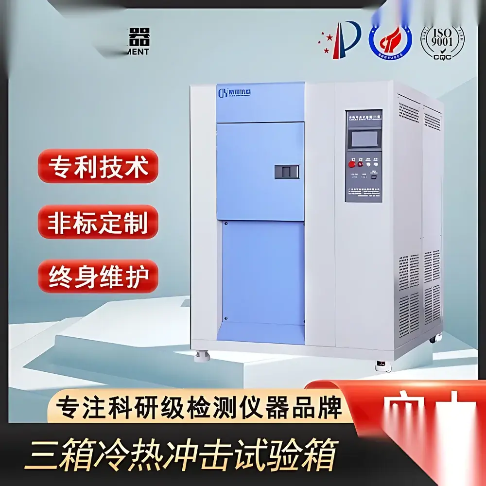
Tri-Segment Thermal Shock Test Chamber
| Brand | OEM |
|---|---|
| Origin | Imported |
| Manufacturer Type | Authorized Distributor |
| Price | USD 12,500 (FOB) |
| Temperature Range Options | A: −20°C to 200°C |
| B | −40°C to 200°C |
| C | −60°C to 200°C |
| Temperature Uniformity in Test Zone | ≤ ±0.5°C (at steady state) |
| High/Low Chamber Temp Stability | ≤ ±2°C |
| Test Zone Dimensions | 450 mm (W) × 300 mm (H) × 300 mm (D) |
| Load Capacity | 20 kg / 30 kg / 50 kg (configurable) |
| Hot Zone Ramp Rate | ~30 min from ambient to 100°C |
| Cold Zone Ramp Rate | ~90 min from ambient to −50°C |
| Transfer Cycle Time | ~6 min (ambient → −40°C), ~5 min (−40°C → ambient), ~5 min (ambient → 85°C) |
| Insulation | High-density fiberglass + fire-retardant PU foam with K-type anti-sweat ducting |
| Construction | Interior & exterior SUS304 stainless steel |
| Actuation | Japanese linear pneumatic cylinder for thermal zone valve control |
| Compliance | Designed to meet ASTM D5229, IEC 60068-2-14, MIL-STD-810H Method 503.7, JIS C 60068-2-14, and CNS 12520 |
Overview
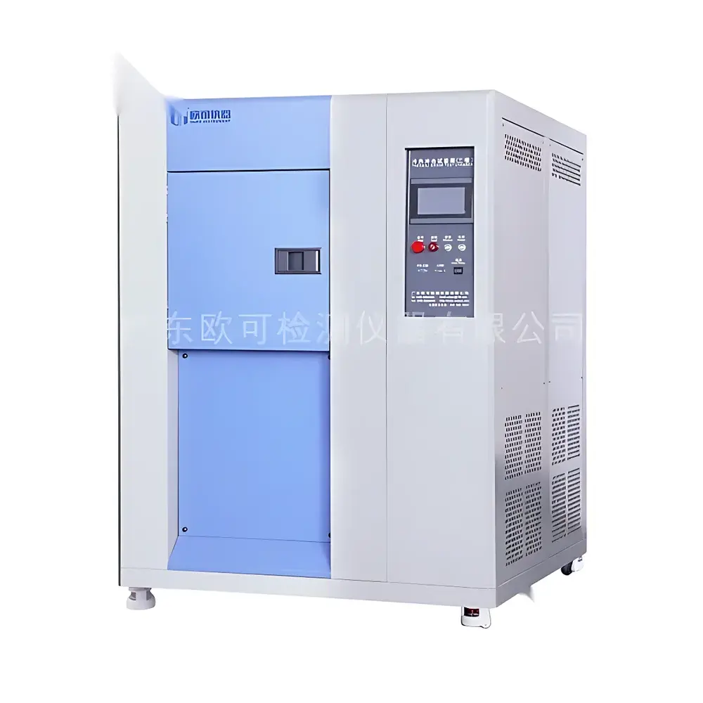
The Tri-Segment Thermal Shock Test Chamber is an engineered environmental reliability testing system designed for rapid, repeatable, and highly controlled thermal cycling between extreme temperature extremes. Unlike single- or dual-chamber configurations, this three-zone architecture—comprising independent high-temperature, low-temperature, and test zones—eliminates thermal mass interference during transitions, enabling precise, high-fidelity shock profiles with minimal overshoot and improved thermal recovery reproducibility. The system operates on the principle of physical zone isolation and pneumatic-driven air transfer, where samples remain stationary in the central test chamber while hot or cold air is actively routed from dedicated蓄热 (heat storage) or蓄冷 (cold storage) chambers via precisely timed, high-cycle-life linear pneumatic actuators. This design ensures strict separation of thermal reservoirs, minimizes cross-contamination of ambient moisture or particulates, and supports stringent qualification requirements for aerospace components, automotive ECUs, power electronics, and high-reliability PCB assemblies.
Key Features
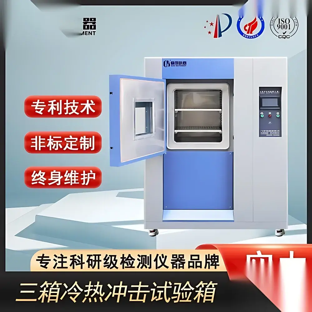
- Three physically isolated thermal zones: independent high-temperature chamber (up to 200°C), low-temperature chamber (down to −60°C), and a dedicated test chamber with adjustable stainless-steel shelf racks
- SUS304 stainless steel interior and exterior construction—corrosion-resistant, non-outgassing, and compliant with cleanroom-compatible surface finish standards (Ra ≤ 0.8 µm)
- High-efficiency insulation system combining fire-retardant polyurethane (PU) foam and high-density mineral fiber, integrated with a proprietary K-type anti-sweat ducting system to prevent condensation migration and thermal bridging
- Pneumatically actuated thermal gate mechanism using JIS-certified linear cylinders for >500,000 cycle durability and sub-second response time in zone isolation control
- Ergonomic service design: front-accessible refrigeration and electrical compartments, modular component layout, and heavy-duty casters rated for ≥300 kg static load
- Standard 50 mm diameter test port with silicone O-ring sealing, rated for operation across full temperature range (−60°C to 200°C), suitable for external power, thermocouple, or data acquisition line feedthrough
- Configurable load capacity options (20 kg / 30 kg / 50 kg) with dual-height-adjustable stainless-steel shelf supports (±20 mm fine positioning)
Sample Compatibility & Compliance
This chamber accommodates rigid and semi-rigid specimens up to 450 mm (W) × 300 mm (H) × 300 mm (D), including printed circuit board assemblies (PCBAs), semiconductor packages (QFP, BGA, CSP), automotive sensors, battery modules, and optoelectronic housings. All internal surfaces are free of volatile organic compounds (VOCs) and halogenated materials, supporting RoHS-compliant and ISO 14644-1 Class 7 cleanroom-adjacent operation. The system is configured to execute standardized thermal shock profiles per ASTM D5229 (for polymer matrix composites), IEC 60068-2-14 (Change of temperature), MIL-STD-810H Method 503.7 (Temperature Shock), JIS C 60068-2-14, and CNS 12520. It supports GLP/GMP-aligned validation protocols—including IQ/OQ/PQ documentation templates—and includes hardware-level support for 21 CFR Part 11-compliant electronic audit trails when paired with optional validated software packages.
Software & Data Management
Equipped with a 10.1-inch capacitive touchscreen HMI running embedded Linux, the controller provides real-time monitoring of all three zone temperatures, pneumatic valve status, compressor discharge pressure, and chamber dew point. Up to 200 programmable test steps can be stored locally, with cycle logging at user-defined intervals (1–60 s). Data export is supported via USB 2.0 (CSV format) or Ethernet (Modbus TCP/IP) for integration into LIMS or MES platforms. Optional PC-based software enables advanced profile sequencing, statistical process control (SPC) charting, alarm event correlation, and automated report generation compliant with ISO/IEC 17025 clause 7.8. All temperature readings are traceable to NIST-calibrated Pt100 RTD sensors (Class A tolerance, ±0.15°C at 0°C), with built-in sensor diagnostics and drift compensation algorithms.
Applications
- Qualification testing of solder joint integrity under accelerated thermal fatigue (IPC-9701A)
- Reliability screening of MEMS devices and wafer-level chip-scale packages (WLCSP)
- Validation of thermal interface material (TIM) performance across −40°C to 125°C cycles
- Environmental stress screening (ESS) for avionics modules prior to HALT/HASS
- Material coefficient of thermal expansion (CTE) mismatch evaluation in multi-layer ceramic capacitors (MLCCs)
- Pre-conditioning of lithium-ion battery cells before safety abuse testing (UN 38.3)
FAQ
What is the typical thermal transition time between −40°C and +85°C in the test zone?
The system achieves a nominal transition from ambient (25°C) to −40°C in ≤6 minutes, and from ambient to +85°C in ≤5 minutes, based on empty chamber conditions per IEC 60068-2-14 Annex B.
Does the chamber support automated calibration verification?
Yes—the controller includes a built-in calibration check mode that verifies RTD channel linearity and offset against reference junctions; full sensor calibration certificates (NIST-traceable) are provided with initial commissioning.
Can the test zone accommodate fixtures with active electrical biasing?
Absolutely—the standard 50 mm test port supports insulated feedthroughs rated for 600 VAC and 10 A continuous, with optional vacuum-tight or EMI-shielded variants available upon request.
Is remote monitoring and alarm notification supported?
Yes—via optional SNMP-enabled Ethernet gateway, users can configure email/SMS alerts for critical events (e.g., compressor fault, door open, temperature deviation >±1.0°C for >30 s).
What maintenance intervals are recommended for the refrigeration system?
Compressor oil analysis and refrigerant purity verification are recommended every 2,000 operating hours; full system leak check and filter-drier replacement every 5,000 hours or biannually—whichever occurs first.


