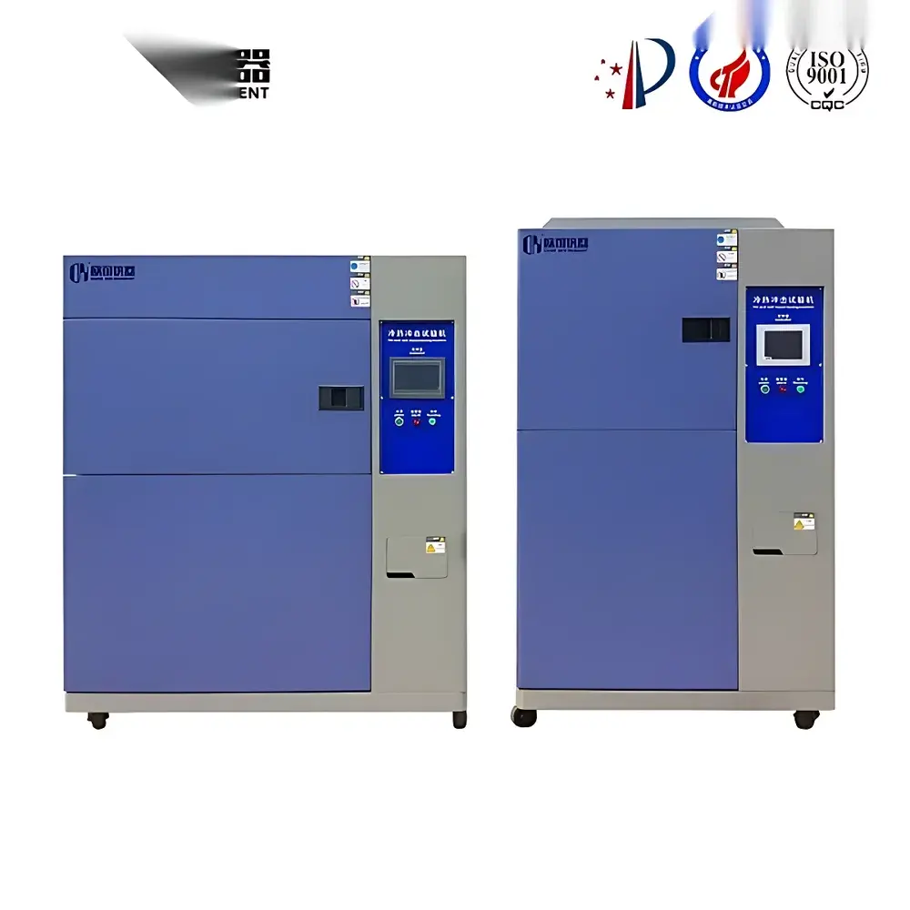
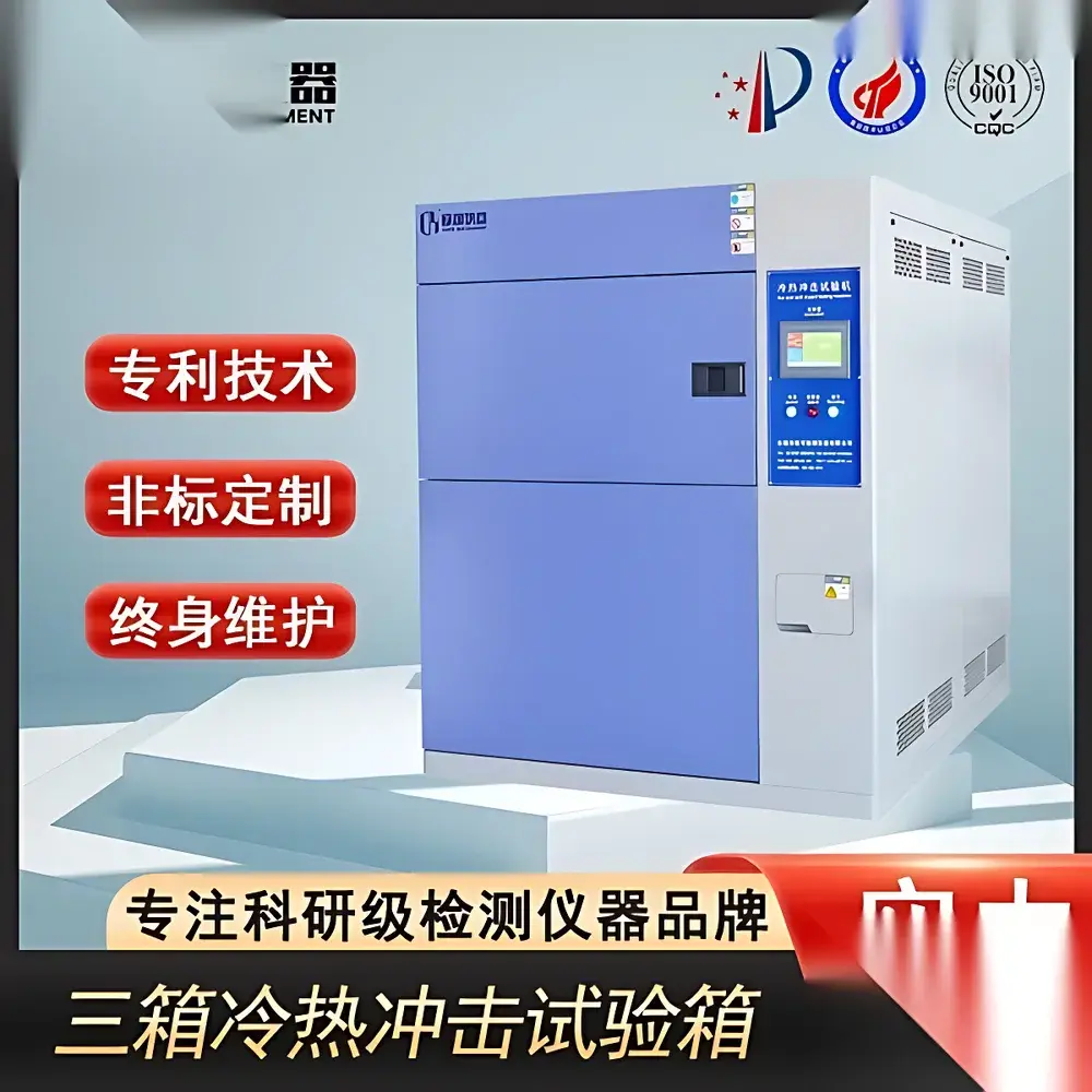
Tri-Segment Thermal Shock Test Chamber
| Brand | Other Brands |
|---|---|
| Origin | Imported |
| Manufacturer Type | General Distributor |
| Price | USD 11,200 (FOB) |
Overview
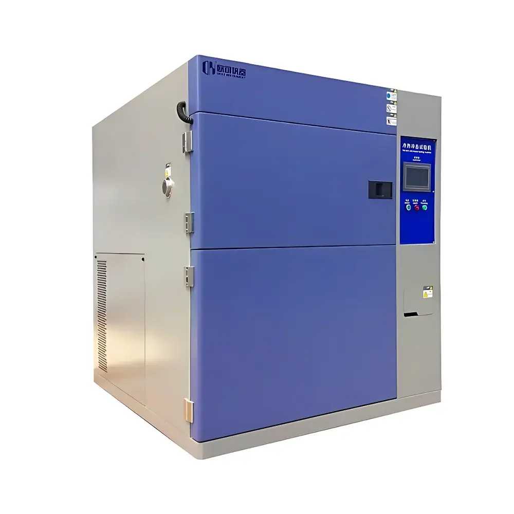
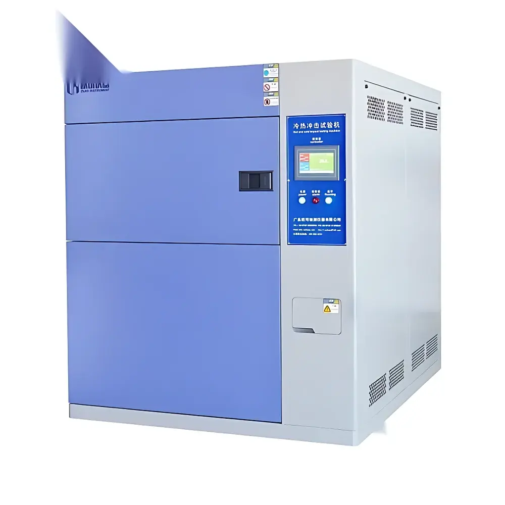
The Tri-Segment Thermal Shock Test Chamber is an engineered environmental test system designed to evaluate material and component reliability under rapid, extreme temperature transitions. Unlike two-chamber or single-chamber thermal shock configurations, this three-compartment architecture—comprising independent high-temperature soak, low-temperature soak, and test specimen chambers—enables true static sample positioning during exposure. Specimens remain stationary in the central test chamber while thermal energy is transferred via controlled air circulation between isolated reservoirs. This design eliminates mechanical stress from moving baskets, minimizes thermal lag, and ensures superior temperature uniformity (±0.5 °C) and stability (±0.3 °C over 60 min), critical for validating solder joint integrity, polymer dimensional stability, and electronic package delamination resistance per MIL-STD-883, JEDEC JESD22-A106, and IEC 60068-2-14.
Key Features
- Three-segment insulated chamber architecture: dedicated hot soak zone (up to +150 °C), cold soak zone (down to −70 °C), and static test zone (−65 °C to +150 °C)
- Dual-stage cascade refrigeration system utilizing imported German semi-hermetic compressors with water-cooled condensers
- Evaporative condenser interstage heat exchanger enabling efficient thermal coupling between high- and low-temperature cycles
- Energy modulation control logic that dynamically adjusts refrigerant flow and compressor loading to maintain target transition rates (e.g., 15 K/min typical transfer rate between zones) without oversizing equipment
- Stainless steel 304 interior construction with non-drip insulation and double-glazed observation window with anti-fog heating
- Integrated safety interlocks including over-temperature cutoff, refrigerant pressure monitoring, and door position verification
Sample Compatibility & Compliance
The chamber accommodates specimens up to 500 mm × 500 mm × 500 mm (W×D×H) with a maximum mass load of 30 kg. It supports standardized thermal shock profiles—including step, ramp, and dwell sequences—as defined in ISO 16750-4 (road vehicles), ASTM D5229/D5229M (composite materials), and IPC-9701A (printed board assemblies). Full compliance is verified against GB/T 2423.22–2002 (Temperature Change), GJB 150.5A–2009 (Military Standard Temperature Shock), and IEC 60068-2-14:2016 (Test N: Change of Temperature). The system meets GLP documentation requirements for traceable calibration records and supports optional validation packages compliant with IQ/OQ protocols per ISO/IEC 17025.
Software & Data Management
Equipped with a programmable 10.1″ TFT touchscreen HMI running embedded Linux, the controller supports up to 99 programmable test profiles with 999 segments each. Real-time data logging records chamber temperatures (hot/cold/test zones), compressor discharge pressures, and fan speeds at user-defined intervals (1–60 s). Export formats include CSV and PDF reports with time-stamped metadata. Optional Ethernet interface enables remote monitoring via Modbus TCP or OPC UA; audit trail functionality satisfies FDA 21 CFR Part 11 requirements when paired with password-protected user roles and electronic signature capability.
Applications
This chamber serves as a core qualification tool in aerospace electronics (DO-160 Section 4.6), automotive ECU validation (SAE J2223), semiconductor packaging (JEDEC J-STD-020), and medical device sterilization cycle development (ISO 11137). It is routinely deployed to assess thermal expansion mismatch in multilayer ceramic capacitors (MLCCs), intermetallic growth kinetics in wire-bonded assemblies, and glass transition behavior in thermoplastic encapsulants. Its static-test-zone configuration is particularly suited for optical components, MEMS sensors, and hermetically sealed modules where vibration-induced misalignment must be avoided.
FAQ
What cooling infrastructure is required for operation?
A dedicated external cooling tower delivering 10 m³/h of water at ≤32 °C inlet temperature is mandatory for the water-cooled condenser circuit.
Can the system perform temperature ramping within a single chamber?
No—this is a true tri-segment shock system optimized for rapid transfer between stable thermal reservoirs; it does not support continuous ramp profiles across the full range.
Is third-party calibration certification available?
Yes—NIST-traceable calibration certificates with uncertainty budgets are provided upon request, covering all PT100 sensors and control loop verification.
What is the typical thermal transition time between extreme setpoints?
From +150 °C to −70 °C in the test chamber requires ≤15 minutes, measured per IEC 60068-2-14 Annex B.
Does the system support automated cycling with dwell periods?
Yes—users may define variable dwell durations (1 min to 999 h) at either extreme temperature before initiating the next transfer phase.


