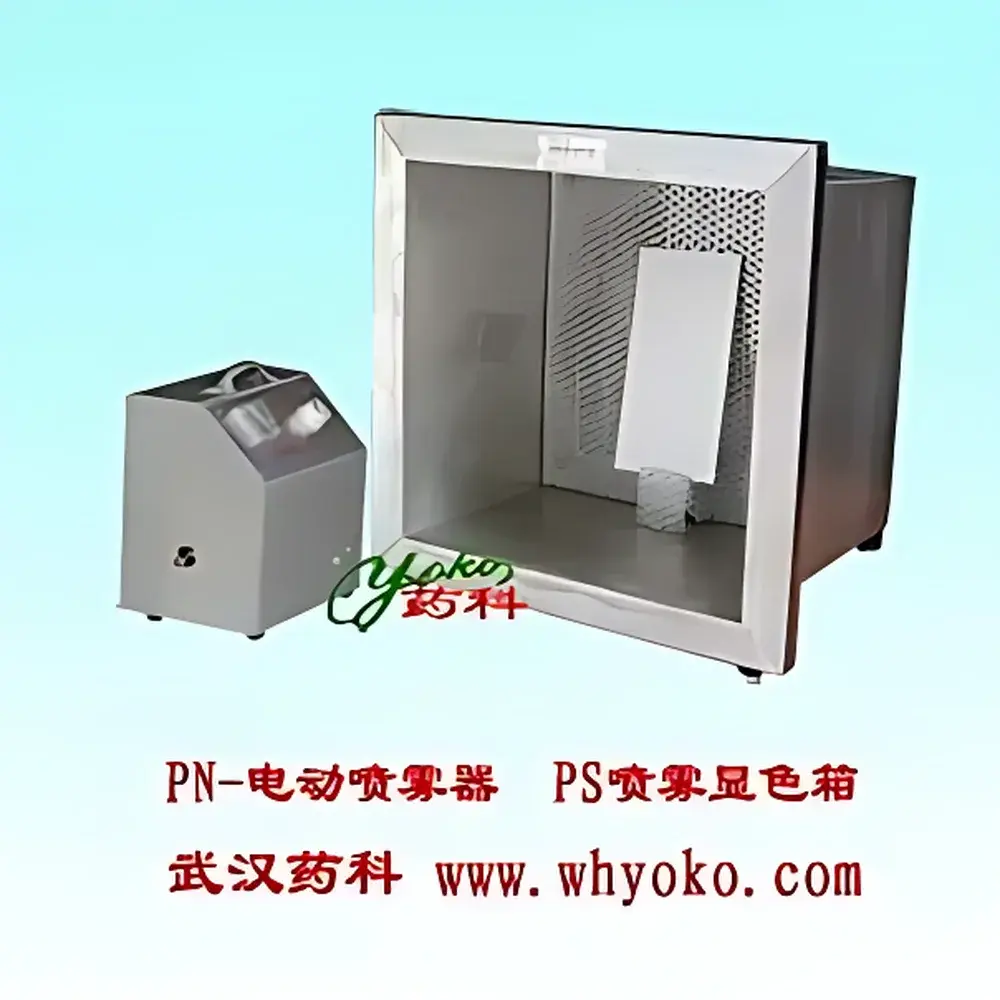
YOKO PX Series TLC Spray Development Chamber
| Brand | whYOKO |
|---|---|
| Model | YOKO-PX |
| Type | Manual Prep-TLC Spray Development Chamber |
| Construction | All-Stainless-Steel Enclosure |
| Exhaust System | Centrifugal Duct Fan |
| Exhaust Capacity | 5000 L/min (PX-A) / 8300 L/min (PX-B) |
| Dimensions | 460 × 460 × 460 mm (PX-A) / 500 × 500 × 500 mm (PX-B) |
| Duct | φ150 mm × 2 m telescopic stainless-steel flex duct with fittings |
| Power | 50 W (PX-A) / 90 W (PX-B) |
| Compliance | Designed for ISO/IEC 17025-aligned lab safety workflows |
| Application | Post-development spray reagent application and acid carbonization in thin-layer chromatography |
Overview
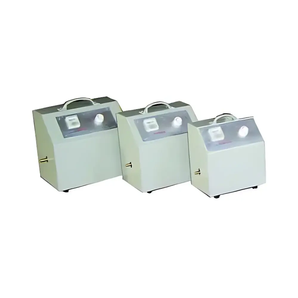
The YOKO PX Series TLC Spray Development Chamber is an engineered containment solution designed specifically for safe, controlled application of visualization reagents—such as sulfuric acid, anisaldehyde, iodine vapor, or ninhydrin solutions—during post-chromatographic development in thin-layer chromatography (TLC). Unlike open-bench spraying, which exposes personnel to hazardous aerosols and risks corrosion of analytical instrumentation and fume hood interiors, the PX chamber provides full enclosure with active exhaust ventilation. Its operation is grounded in fundamental laboratory containment principles: negative pressure differential maintenance via centrifugal duct fan suction, laminar airflow management within the chamber volume, and physical barrier isolation of volatile, corrosive, or cytotoxic reagents. The device serves not only as a dedicated spray station but also supports GLP-compliant documentation of reagent exposure conditions when integrated into validated TLC workflows.
Key Features
- All-welded 304 stainless-steel construction ensures long-term resistance to acid corrosion, solvent degradation, and routine decontamination protocols.
- Integrated high-efficiency centrifugal duct fan delivers consistent volumetric exhaust flow (5000 L/min for PX-A; 8300 L/min for PX-B), maintaining stable negative pressure across the working aperture.
- Telescopic φ150 mm stainless-steel exhaust duct (2 m length, with universal swivel fittings) enables flexible routing to existing lab exhaust manifolds or dedicated scrubber systems.
- Front-access transparent polycarbonate viewing window (10 mm thick, chemical-resistant grade) allows real-time observation without compromising containment integrity.
- Removable stainless-steel tray with raised edge facilitates spill containment and simplifies residue removal between runs.
- Compact footprint (460 mm³ or 500 mm³ variants) optimizes benchtop space while meeting ANSI Z9.5 and EN 14175-3 laboratory ventilation design guidelines for local exhaust devices.
Sample Compatibility & Compliance
The PX chamber accommodates standard TLC plates (up to 20 × 20 cm), preparative silica gel plates (e.g., 20 × 20 cm or 10 × 20 cm), and aluminum-backed or glass-backed substrates. It is compatible with all common TLC visualization reagents—including concentrated H2SO4, ethanolic KOH, p-anisaldehyde/H2SO4, vanillin/H2SO4, and chlorinated solvent-based sprays—without risk of chamber degradation. From a regulatory standpoint, the system supports compliance with OSHA 1910.1200 (Hazard Communication), EU CLP Regulation (EC No. 1272/2008), and ISO 15190:2020 (medical laboratories — requirements for safety). When used in conjunction with documented SOPs, it contributes to audit readiness for FDA 21 CFR Part 11–governed environments where traceability of reagent handling steps is required.
Software & Data Management
As a manually operated containment device, the YOKO PX Series does not incorporate embedded firmware or digital interfaces. However, its mechanical design enables seamless integration into electronic lab notebook (ELN) and LIMS ecosystems: users may log spray parameters—including reagent identity, concentration, volume applied, dwell time, and post-spray heating conditions—directly against associated TLC run IDs. Optional barcode-labeled chamber usage logs can be generated for internal QA tracking. For labs operating under GLP or GMP frameworks, the unit’s passive design eliminates validation overhead related to software, while its durable construction ensures consistent performance across >10,000 operational cycles without recalibration.
Applications
- Safe application of charring reagents (e.g., 10% H2SO4 in ethanol) prior to thermal development on silica or alumina plates.
- Controlled iodine vapor exposure for reversible compound detection in natural product screening.
- Uniform spraying of derivatizing agents (e.g., o-phthalaldehyde for amino acid detection) under reproducible airflow conditions.
- Secondary reaction chamber for small-scale oxidative or hydrolytic treatments where solvent evaporation must be managed.
- Containment platform for method development involving novel visualization chemistries requiring operator safety assessment per ICH Q5C and Q9 principles.
FAQ
Is the PX chamber suitable for use with flammable solvents such as chloroform or diethyl ether?
Yes—provided the exhaust duct is connected to a spark-proof, explosion-rated lab exhaust system compliant with NFPA 45 and local fire codes. The stainless-steel housing itself is non-reactive and static-dissipative when properly grounded.
Can the chamber be retrofitted with a built-in UV lamp for simultaneous visualization?
No—the PX series is designed exclusively as a spray containment unit. Integration of UV illumination would compromise structural integrity and airflow dynamics; separate UV cabinets (e.g., CAMAG UV254/366) are recommended for orthogonal detection.
What maintenance is required for the centrifugal fan assembly?
Annual inspection of impeller balance and bearing lubrication is advised. Filter-free operation eliminates consumables, but duct interior should be inspected quarterly for particulate buildup using borescope imaging.
Does the unit meet CE marking requirements for export to the European Union?
The PX-A and PX-B models comply with the essential health and safety requirements of the Machinery Directive 2006/42/EC and the Electromagnetic Compatibility Directive 2014/30/EU when installed per manufacturer instructions and connected to certified exhaust infrastructure.