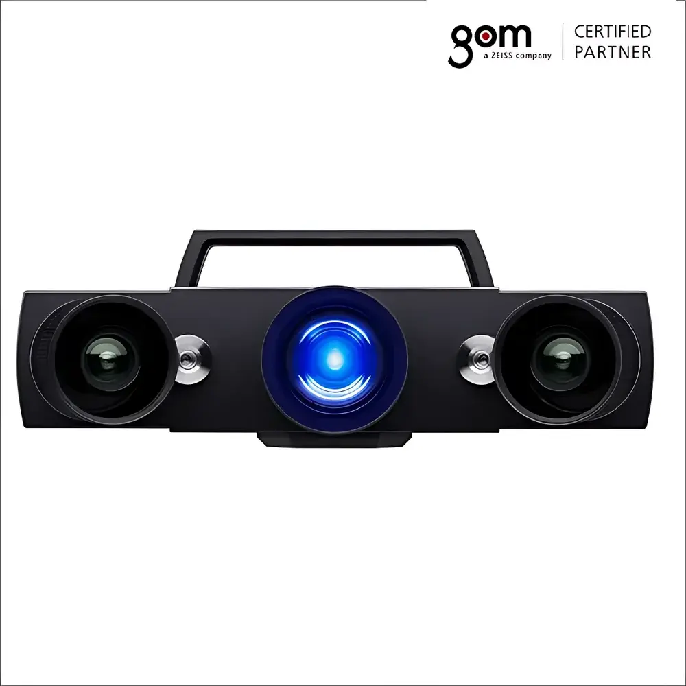
ZEISS ATOS Q 3D Scanner
| Brand | ZEISS |
|---|---|
| Origin | Germany |
| Model | ATOS Q |
| Type | Optical 3D Coordinate Measuring System |
| Measurement Principle | Triple-camera triangulation with fringe projection (3-in-1 sensor head) |
| Weight | 4 kg (sensor head only) |
| Compliance | ISO 10360-8, VDI/VDE 2634 Part 2, ASTM E2924 |
| Software Platform | GOM Inspect Pro (with GD&T, mesh comparison, deviation analysis, and automated reporting) |
Overview
The ZEISS ATOS Q is a high-precision optical 3D coordinate measuring system engineered for industrial metrology applications requiring traceable, repeatable, and fully documented dimensional verification. Based on structured light fringe projection and triple-camera triangulation (3-in-1 sensor architecture), the ATOS Q captures full-field surface topography by projecting calibrated sinusoidal light patterns onto the part while simultaneously acquiring synchronized images from three high-resolution CMOS sensors—two lateral cameras and one central camera. This multi-view acquisition eliminates blind spots, reduces the need for repositioning, and significantly improves measurement robustness on reflective or glossy surfaces without requiring spray-based matting agents. The system operates as a non-contact, high-density point cloud generator, delivering sub-micron-level depth resolution and micron-class volumetric accuracy across its working volume—enabling direct comparison against CAD geometry for first-article inspection, tool validation, reverse engineering, and production process control.
Key Features
- Triple-sensor head architecture (3-in-1): Simultaneous capture from three independent viewpoints ensures comprehensive coverage in a single scan pass—even for complex freeform geometries with undercuts and deep cavities.
- Self-monitoring metrology engine: Real-time monitoring of sensor calibration status, environmental lighting conditions, and mechanical stability during acquisition; automatic compensation for ambient light fluctuations and thermal drift.
- Integrated online recalibration: Continuous in-scan verification of system parameters—including lens distortion, projector alignment, and stereo geometry—ensuring measurement integrity throughout extended sessions.
- Lightweight, portable design: Sensor head weighs only 4 kg and is optimized for handheld, tripod-mounted, or robotic integration; carbon-fiber support structures minimize thermal expansion and vibration transmission.
- Modular automation readiness: Compatible with GOM ROT 350 rotary tables for semi-automated scanning, and fully integrated with ATOS ScanBox 4105 for turnkey automated metrology cells.
- Virtual Measuring Room (VMR) capability: ScanBox 4105 includes offline programming software that simulates robot kinematics, sensor positioning, collision avoidance, and optimal scan path generation—no robotics expertise required for deployment.
Sample Compatibility & Compliance
The ATOS Q accommodates parts ranging from small precision components (e.g., turbine blades, medical implants, injection-molded housings) to medium-sized assemblies (up to ~1.5 m in diagonal dimension), provided adequate working distance and surface reflectivity fall within the validated operating envelope. Matte, satin-finished, or lightly textured surfaces yield optimal results; highly specular or transparent materials may require standardized matte sprays compliant with ISO 8502-3. All measurement workflows adhere to international standards including ISO 10360-8 (performance verification of optical CMMs), VDI/VDE 2634 Part 2 (optical 3D measuring systems), and ASTM E2924 (standard guide for 3D imaging metrology). Data provenance and audit trails meet GLP/GMP documentation requirements when used with GOM Inspect Pro’s 21 CFR Part 11-compliant configuration.
Software & Data Management
GOM Inspect Pro serves as the native software platform, offering a complete metrology workflow—from raw point cloud generation and polygonal mesh reconstruction to GD&T evaluation (per ASME Y14.5 / ISO 1101), nominal-actual deviation mapping, cross-section analysis, and automated report generation in PDF, HTML, or XML formats. The software supports bidirectional CAD import (STEP, IGES, JT, CATIA, NX, Creo), mesh editing tools for hole filling and smoothing, and scripting via Python API for custom inspection routines. All measurement data—including raw images, calibration logs, environmental metadata, and operator annotations—is stored in a structured project file format with embedded digital signatures and version history, ensuring full traceability and compliance with quality management system (QMS) requirements.
Applications
- First-article inspection and PPAP submission in automotive and aerospace supply chains
- Die and mold validation, including cavity wear analysis and shrinkage assessment
- Reverse engineering of legacy parts lacking CAD documentation
- Production line quality gate checks with pass/fail decision logic based on user-defined tolerance zones
- Tooling certification and maintenance monitoring for stamping dies, composite layup molds, and injection tools
- Deformation analysis under thermal or mechanical load using time-series 3D scans
FAQ
Does the ATOS Q require periodic factory recalibration?
Yes—annual traceable recalibration against NIST-traceable artifacts is recommended per ISO/IEC 17025 guidelines. Field verification using certified reference spheres or step gauges can be performed daily or per-shift using built-in GOM calibration routines.
Can the ATOS Q measure black or shiny surfaces without surface preparation?
High-gloss or low-reflectivity surfaces remain challenging for fringe projection systems. While ATOS Q’s adaptive illumination and multi-angle capture improve performance on moderately reflective parts, matte spray application remains necessary for reliable results on mirror-finish metals or carbon fiber composites.
Is GOM Inspect Pro compatible with enterprise PLM or MES systems?
Yes—via standardized interfaces including RESTful APIs and export modules for Teamcenter, Windchill, and Siemens Opcenter Quality, enabling seamless integration into digital thread workflows and centralized quality analytics dashboards.
What is the typical measurement uncertainty for a 500 mm calibration sphere?
Under controlled lab conditions (20 ± 0.5 °C, ISO Class 6 cleanroom), the expanded uncertainty (k=2) for diameter measurement is ≤ 2.8 µm, verified per ISO 10360-8 Annex D protocols.
How does the Virtual Measuring Room reduce commissioning time for automated cells?
VMR enables complete offline simulation of robot trajectories, sensor poses, and collision-free scan sequences—reducing on-site commissioning time by up to 70% and eliminating costly physical trial runs during cell integration.