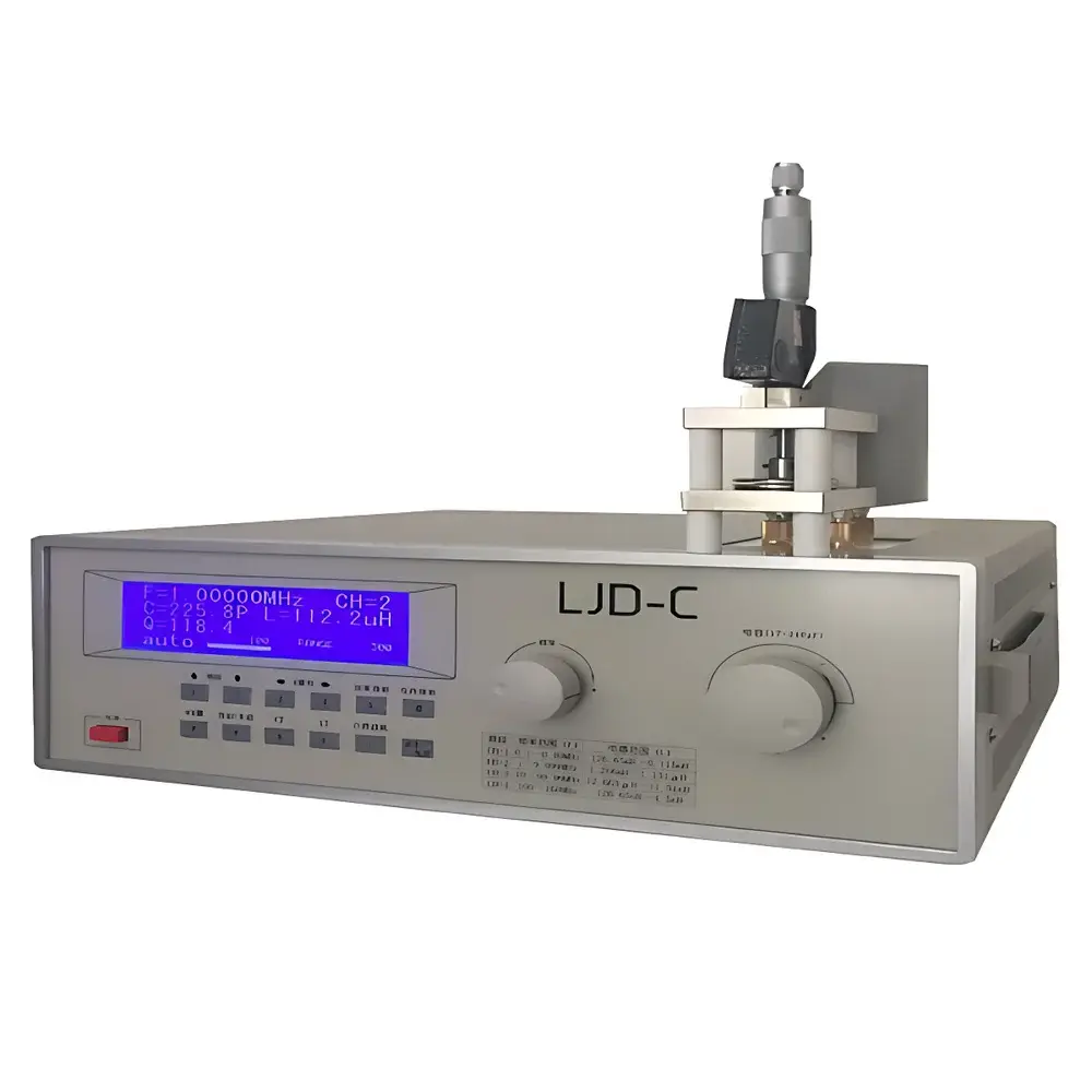
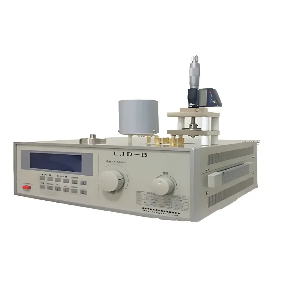
Zhonghang Dingli LJD Series Direct-Reading Dielectric Constant and Dissipation Factor Meter
| Brand | Zhonghang Dingli |
|---|---|
| Origin | Beijing, China |
| Model | LJD Series Direct-Reading |
| Measurement Principle | Resonant Frequency Shift Method (Q-Meter Based) |
| Frequency Range | 10 kHz – 10 MHz (typical for LJD-B/C variants) |
| Capacitance Measurement Range | 0.1 pF – 2.5 µF (LJD-B), 0.1 pF – 25 nF (LJD-C) |
| Resolution | 0.1 pF |
| Dielectric Loss Tangent (tan δ) Accuracy | ±0.0001 (at optimal Q > 100) |
| Compliance | Designed per GB/T 1409–2006 (Chinese national standard equivalent to IEC 60250), supports ASTM D150 and ISO 257-1/2 test methodologies |
Overview
The Zhonghang Dingli LJD Series Direct-Reading Dielectric Constant and Dissipation Factor Meter is a precision benchtop instrument engineered for rapid, non-destructive characterization of dielectric properties in solid, liquid, and powdered insulating materials. It operates on the resonant frequency shift principle using a calibrated Q-meter architecture—leveraging high-stability variable capacitors, precision inductors, and digital frequency synthesis to determine complex permittivity (ε* = ε′ − jε″) via measurement of capacitance (Cx) and dissipation factor (tan δ). Unlike impedance analyzers or broadband spectrometers, the LJD series employs a fixed-frequency or swept-frequency parallel-resonant LC circuit configuration, enabling direct readout of relative permittivity (εr) and loss tangent without iterative curve fitting. Its design targets laboratories requiring traceable, repeatable measurements under controlled environmental conditions (23 ± 2 °C, <65% RH), particularly in QC/QA environments for polymer composites, ceramic substrates, transformer oils, and capacitor dielectrics.
Key Features
- Direct-reading analog/digital display of εr and tan δ—no external calculation or software conversion required
- Dual-mode capacitance measurement: parallel substitution method (for Cx < main tuning capacitor) and CT (capacitance tracking) mode (for Cx > main tuning range), supporting up to 2.5 µF (LJD-B) or 25 nF (LJD-C)
- High-resolution 0.1 pF capacitance detection, enabled by fine-step variable capacitor and stabilized RF oscillator
- Natural resonance frequency (f2) determination algorithm for accurate stray capacitance (C0) compensation—critical for high-Q inductor and low-loss material evaluation
- Integrated auxiliary inductor set (LKI-L series) for standardized test setup, minimizing operator-induced variability
- Front-panel frequency search function with automatic resonance lock and Q-value maximization feedback
- Robust mechanical architecture with shielded RF cavity, low-noise grounding path, and temperature-compensated calibration reference components
Sample Compatibility & Compliance
The LJD meter accommodates standard ASTM D150-compliant electrode configurations—including parallel-plate (for solids ≥0.5 mm thick), liquid cells (with guarded electrodes), and powder holders with compression fixtures. Sample geometry must ensure uniform electric field distribution; thickness tolerance is ±0.02 mm for εr accuracy ≤±1.5%. The instrument conforms to GB/T 1409–2006 (equivalent to IEC 60250:1969 + A1:1985), and its measurement traceability aligns with national metrological verification规程 JJG 557–2011 (Q-Meter Calibration Specification). While not inherently 21 CFR Part 11 compliant, audit-ready data logging can be implemented via optional RS-232 output and third-party GLP/GMP-compliant acquisition software. All test procedures support full documentation of calibration date, operator ID, ambient temperature/humidity, and electrode spacing—essential for ISO/IEC 17025-accredited labs.
Software & Data Management
The LJD series operates as a standalone hardware platform with no embedded operating system. Raw readings (Cx, fres, Q, tan δ) are displayed on a dual-line LCD with manual data recording. For automated reporting, optional RS-232 serial interface enables integration with LabVIEW, MATLAB, or custom Python scripts using SCPI-like command syntax (e.g., “READ?”, “FREQ?”). Exported datasets include timestamp, measurement mode flag (SUB/CT), and user-entered sample ID. When deployed in regulated environments, users may implement electronic signatures and audit trails via external LIMS or ELN systems—consistent with FDA expectations for data integrity under ALCOA+ principles (Attributable, Legible, Contemporaneous, Original, Accurate, Complete, Consistent, Enduring, Available).
Applications
- Quality control of epoxy resins, polyimide films, and PTFE-based PCB laminates during incoming inspection and process validation
- Determination of moisture content in transformer oil via tan δ elevation at 90 °C (per IEC 60296)
- Characterization of ferroelectric ceramics (e.g., BaTiO3) across temperature-dependent εr transitions
- Screening of nanocomposite dielectrics for high-voltage insulation applications
- Verification of coating uniformity and void fraction in multilayer capacitor dielectrics
- Educational use in university physics and materials science labs for fundamental permittivity experiments
FAQ
What is the primary measurement principle used by the LJD meter?
It utilizes the resonant frequency shift method in a parallel LC circuit, where changes in sample capacitance and conductance alter both the resonant frequency and Q-factor—enabling simultaneous extraction of ε′ and ε″.
Can the LJD measure materials with very low loss (tan δ < 0.001)?
Yes—when combined with high-Q reference inductors (Q > 300) and optimized electrode geometry, the instrument achieves tan δ resolution down to 0.0001, provided ambient electromagnetic interference is minimized.
Is calibration traceable to national standards?
Factory calibration follows GB/T 1409–2006 and uses NIM-traceable capacitance standards; annual recalibration is recommended per JJG 557–2011.
Does the system support temperature-controlled measurements?
No built-in thermal chamber—but the instrument is compatible with external environmental chambers (e.g., ESPEC SU-261) when paired with temperature-stable electrodes and shielded cabling.
How is stray capacitance (C0) compensated during high-accuracy testing?
Through the natural resonance frequency (f2) method: repeated insertion/removal of the test coil while adjusting C1 until resonance remains invariant, yielding C0 = C1(f1/f2)² / [1 − (f1/f2)²].


