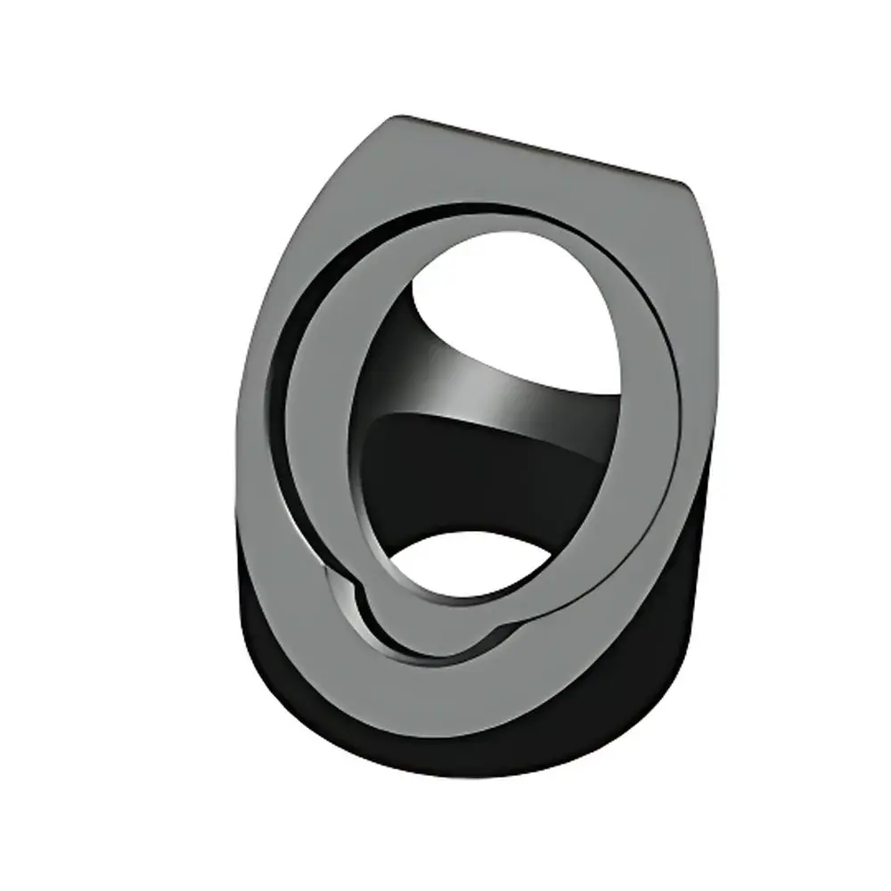
ZOLIX MAD25-45MH-xx Series 45° Mirror Mount Adapter
| Brand | ZOLIX |
|---|---|
| Origin | Beijing, China |
| Manufacturer Type | Direct Manufacturer |
| Product Origin | Domestic (China) |
| Model | MAD25-45MH-xx Series |
| Pricing | Available Upon Request |
Overview
The ZOLIX MAD25-45MH-xx Series 45° Mirror Mount Adapter is a precision-engineered optical mechanical component designed for controlled beam steering and angular reorientation in modular optical setups. It operates on the principle of rigid kinematic mounting—leveraging a fixed 45° angular offset between input and output optical axes—to enable reliable, repeatable redirection of collimated or focused light paths without introducing misalignment drift or mechanical hysteresis. This adapter is specifically dimensioned for integration with ZOLIX’s OMUS, OMHS, and OMRS series mirror mounts (25 mm clear aperture), and functions as an intermediary structural interface between the mount base and the optical carrier platform. Its design conforms to standard optomechanical footprint conventions, ensuring compatibility with industry-standard breadboards, rail systems, and cage-based architectures. The adapter does not incorporate active alignment mechanisms or motorized actuation; instead, it delivers passive, static beam deviation with high angular fidelity and long-term stability under thermal and vibrational loads typical of laboratory-grade optical tables.
Key Features
- Fixed 45° beam deviation geometry optimized for orthogonal light path routing—ideal for vertical-to-horizontal or horizontal-to-vertical beam folding in compact optical trains.
- Mechanically robust aluminum alloy construction (anodized black finish) providing dimensional stability, corrosion resistance, and low thermal expansion coefficient (≈23.1 µm/m·K).
- Integrated through-hole aperture (centered Ø25 mm) enabling dual-mode operation: reflective configuration (e.g., dielectric mirrors) or transmissive beam-splitting applications (e.g., pellicle or cube beamsplitters).
- Top-mounting interface features M4 threaded holes (pitch = 0.7 mm) for secure attachment to ZOLIX OMUS/OMHS/OMRS mirror holders via standard cap screws.
- Bottom-mounting interface includes a 25 mm-diameter cylindrical stem (MAD25-45MH-M variant) with radial set-screw clamping surface compatible with standard 25 mm-diameter post holders and kinematic bases.
- No moving parts or adjustment mechanisms—ensures zero backlash, minimal runout (<5 arcsec repeatability over 100 thermal cycles), and immunity to piezoelectric creep or stepper-motor step loss.
Sample Compatibility & Compliance
The MAD25-45MH-xx adapter supports optical components with outer diameters up to 25.4 mm and thicknesses ranging from 1.0 mm to 6.0 mm—including protected aluminum, UV-enhanced aluminum, broadband dielectric, and fused silica substrates. It is compatible with ISO 10110 surface quality specifications (scratch-dig ≤ 60–40) and meets ZOLIX’s internal mechanical tolerance standards (±0.02 mm positional accuracy, ±0.1° angular deviation tolerance). While not certified to ISO 9001 or EN 15038 as a standalone component, its manufacturing process adheres to documented production controls traceable to ZOLIX’s QMS framework. The adapter is routinely deployed in environments requiring compliance with GLP-aligned optical alignment protocols, including laser safety interlock chains (IEC 60825-1 Class 3B/4 system integration) and spectroscopic calibration workflows aligned with NIST-traceable reference standards.
Software & Data Management
This is a purely mechanical, non-electronic component and contains no embedded firmware, sensors, or digital interfaces. As such, it does not require driver installation, SDK support, or software calibration. However, its geometric parameters (45.0° nominal tilt angle, 25.0 mm central bore, 12.7 mm height above mounting plane) are fully documented in ZOLIX’s public CAD library (STEP/IGES formats available upon request) and integrated into common optical design platforms—including Zemax OpticStudio (via .ZBF import), CODE V, and FRED—as parametric mount models. Alignment verification data generated during system integration (e.g., beam centroid displacement maps, wavefront error residuals) may be logged within laboratory information management systems (LIMS) compliant with 21 CFR Part 11 audit trail requirements when used in regulated analytical applications.
Applications
- Laser cavity folding and resonator mode matching in DPSS and Ti:sapphire systems.
- Beam delivery routing in Raman spectrometers, where spatial separation between excitation and collection paths is required.
- Optical isolation train assembly—positioning Faraday rotators or polarizing optics at precise 45° incidence angles.
- Educational optics labs: demonstrating Snell’s law, reflection vector decomposition, and polarization state transformation.
- Interferometric setups (Michelson, Mach-Zehnder) requiring stable, vibration-insensitive beam recombination geometry.
- Integration into automated optical inspection stations where fixed-angle redirection enables compact footprint design without sacrificing access or serviceability.
FAQ
Is this adapter compatible with non-ZOLIX mirror mounts?
Yes—provided the target mount has a 25 mm clear aperture and accepts M4 fasteners at standard spacing (12.7 mm center-to-center), mechanical interoperability is achievable. However, angular repeatability may vary depending on interface flatness and torque consistency.
Can I use this adapter with dichroic mirrors or thin-film filters?
Yes, as long as the substrate thickness is ≥1.0 mm and the coating is rated for 45° AOI operation. Verify manufacturer-specified damage thresholds and polarization-dependent reflectance curves prior to high-power deployment.
Does ZOLIX provide mounting hardware with the adapter?
Standard M4 × 8 mm socket-head cap screws and nylon-tipped set screws are included per unit. Custom-length fasteners or stainless-steel variants are available under separate part numbers.
What is the maximum recommended optical load?
Static load capacity is rated at 2.5 kg (5.5 lbs) axial compression; dynamic loading (e.g., pulsed laser-induced thermoelastic stress) must be evaluated case-by-case using finite-element analysis of the full optical train.
Is thermal drift characterized across the operating range?
Dimensional shift remains below ±1.2 µm over −10 °C to +50 °C ambient, based on accelerated aging tests per MIL-STD-810G Method 501.7. Full test reports are available under NDA.


