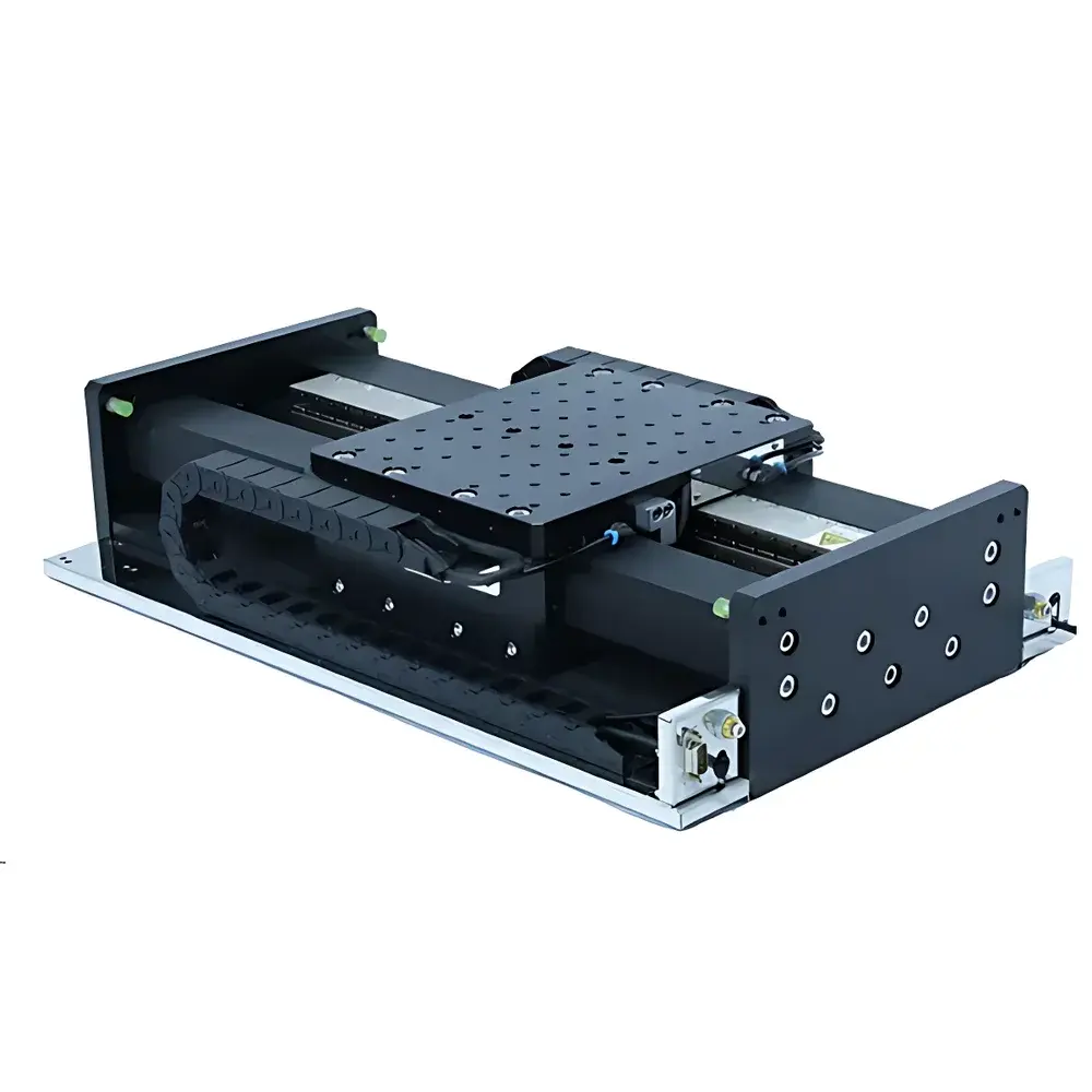
ZOLIX QF Series Air Bearing Linear Translation Stage
| Brand | ZOLIX |
|---|---|
| Model | QF Series |
| Type | Motorized Air-Bearing Translation Stage |
| Base Material Options | Aluminum (A), Granite (S), Silicon Carbide (C) |
| Guide Type | Aerostatic (Air Float) Linear Bearing |
| Drive | Coreless Linear Motor |
| Encoder Resolution | 20 nm |
| Bidirectional Repeatability | ≤ 0.3 µm |
| Straightness | 1–5 µm (depending on travel and base material) |
| Pitch/Yaw | ≤ 4.5 arcsec |
| Load Capacity | 10–15 kg/µm |
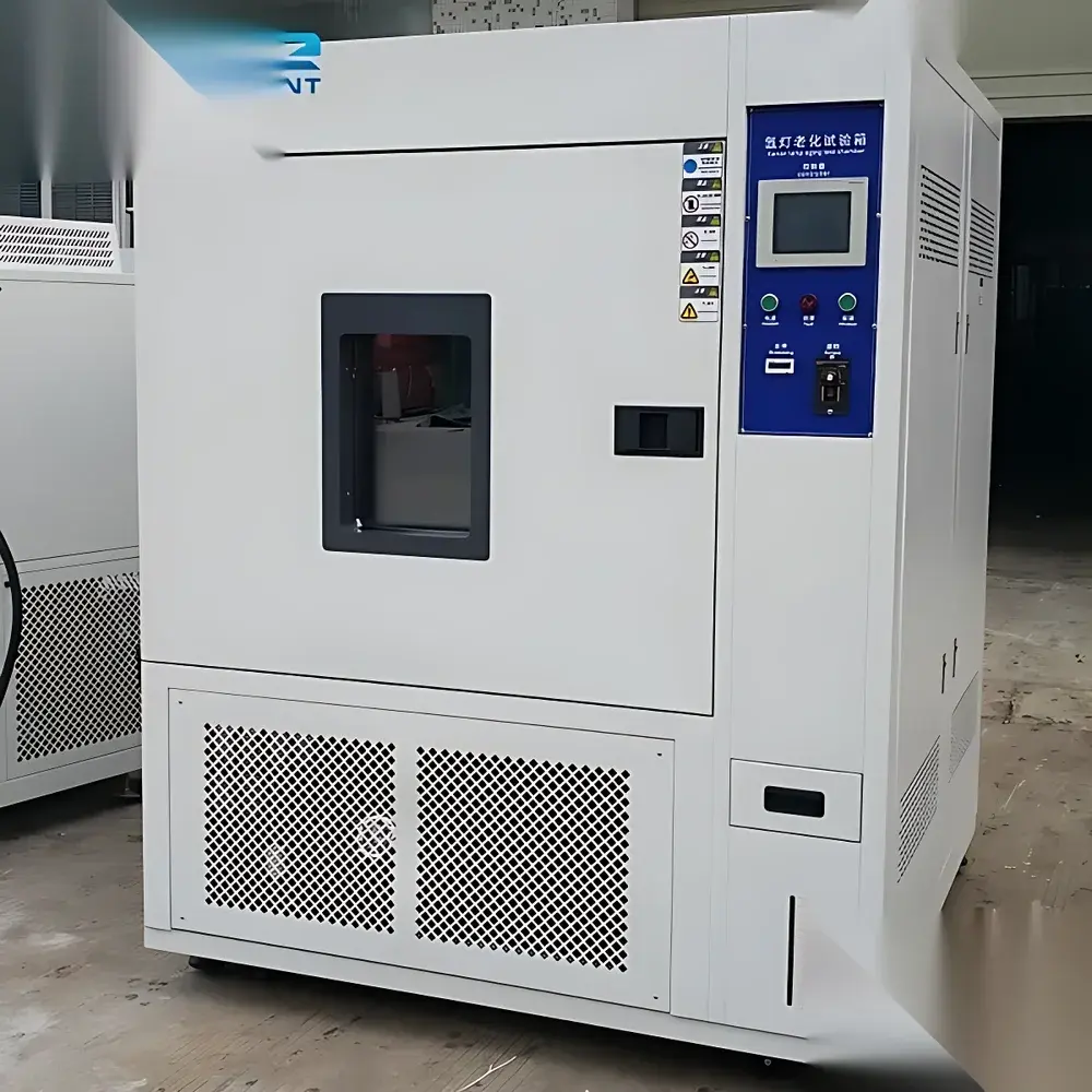
| Operating Environment | Class 10,000–100,000 Cleanroom, 20 ± 1 °C, 40–60% RH, 0.5 MPa Filtered & Dried Compressed Air |
| Compliance | GB/T 17421.2 (Geometric Accuracy Testing of Machine Tools), ISO 230-2 (Test Code for Positioning Accuracy) |
Overview
The ZOLIX QF Series Air Bearing Linear Translation Stage is an ultra-precision motion platform engineered for sub-micron positioning stability in demanding optical, semiconductor, and metrology applications. It operates on the principle of aerostatic (gas-film) support—where a controlled, high-purity compressed air supply generates a uniform, non-contact pressure film between the moving carriage and the guideway. This eliminates mechanical contact, resulting in zero static friction, no particle generation, and complete absence of stick-slip (crawling) behavior. Combined with a coreless linear motor drive and high-resolution interferometric or optical encoder feedback (20 nm resolution standard), the QF stage delivers exceptional trajectory fidelity, minimal velocity ripple, and deterministic position control across its full travel range (100–800 mm). Its structural architecture—available with aluminum, granite, or silicon carbide base materials—is optimized for thermal stability, dynamic stiffness, and vibration attenuation, making it suitable for integration into multi-axis nanopositioning systems, interferometer alignment setups, lithography tool calibration stations, and advanced photonics test benches.
Key Features
- Aerostatic linear bearing system ensures frictionless motion, zero wear, and maintenance-free operation under cleanroom conditions.
- Coreless linear motor provides smooth force delivery, negligible cogging, and precise current-controlled thrust—enabling stable low-speed scanning and high-acceleration moves.
- Standard 20 nm optical encoder resolution supports closed-loop sub-100 nm positioning repeatability (≤ 0.3 µm bidirectional) and ≤ 1.2 µm uncorrected absolute accuracy.
- Modular design accommodates single-axis (QF), XY dual-stage (QFD), and龙门 (gantry-type, QFH) configurations with standardized mounting interfaces (M6/M4 tapped holes on top and bottom surfaces).
- Base material selection (aluminum, granite, or silicon carbide) allows performance tailoring: aluminum for lightweight integration; granite for enhanced damping and thermal mass; silicon carbide for extreme stiffness and CTE matching in vacuum or cryogenic environments.
- Compliant with GB/T 17421.2 geometric accuracy testing methodology using bi-axial line fitting, validated under VC-C grade vibration isolation and ISO Class 10,000–100,000 cleanroom conditions.
Sample Compatibility & Compliance
The QF Series is designed for use with optical components (lenses, mirrors, gratings), photomasks, wafer carriers, and sensor modules requiring nanoscale registration. Its non-outgassing construction (anodized aluminum, sealed granite, or ceramic bases), absence of lubricants, and compatibility with filtered, dried 0.5 MPa compressed air meet stringent requirements for semiconductor front-end equipment and EUV optics handling. The stage conforms to ISO 230-2 for positioning accuracy verification and supports traceable calibration protocols aligned with ISO/IEC 17025 laboratory accreditation standards. While not intrinsically certified for FDA or IEC 61000-4 compliance, its electromagnetic compatibility profile permits integration into Class I medical device test systems when deployed with appropriate external shielding and grounding per IEC 60601-1 Annex DD.
Software & Data Management
The QF Series is compatible with industry-standard motion controllers including TMC-NET-2L, Aerotech A3200, and PI Mercury Motion Control platforms. All models support ASCII-based serial command sets (e.g., “MOV X 10.0000”) and EtherCAT or RS-422 communication interfaces for real-time trajectory streaming. Encoder data output is available in quadrature TTL or SSI format, enabling synchronization with external acquisition systems such as lock-in amplifiers or time-resolved detectors. Firmware includes built-in error logging, thermal drift compensation tables (user-definable per temperature zone), and audit-trail-capable position history buffers—facilitating GLP/GMP-aligned validation documentation per 21 CFR Part 11 when paired with compliant host software.
Applications
- Nanopositioning in laser interferometry and heterodyne measurement systems
- Wafer inspection and mask alignment in photolithography prototyping
- Active stabilization of optical cavities and cavity ring-down spectroscopy platforms
- Multi-axis coordinate measuring machine (CMM) probe calibration stages
- High-stability beam steering and focus scanning in ultrafast laser labs
- Integration into vacuum-compatible metrology tools (with optional stainless-steel seals and bake-out rated components)
FAQ
What compressed air specifications are required for stable operation?
A minimum supply pressure of 0.5 MPa (±0.02 MPa), filtered to ISO 8573-1 Class 2:2:2 (particle size ≤ 0.1 µm, dew point ≤ −40 °C), is mandatory. Oil-free compressors and coalescing + desiccant filtration are strongly recommended.
Can the QF stage operate in vacuum environments?
Standard models are not vacuum-rated; however, custom variants with vacuum-compatible seals, outgassing-tested materials, and dry-running air bearings are available upon engineering review.
Is thermal drift compensated in real time?
Yes—integrated temperature sensors feed into user-configurable compensation algorithms within supported controllers; factory-characterized coefficients for aluminum and granite bases are provided.
How is bidirectional repeatability verified?
Per GB/T 17421.2 Clause 5.3.2, using bi-axial line fitting on encoder data collected over ≥ 30 bidirectional traverses at five equally spaced positions across full travel, under VC-C isolation and controlled ambient conditions.
What is the maximum payload before stiffness degradation becomes significant?
Static load capacity is specified as 10–15 kg/µm deflection; for dynamic applications involving acceleration > 0.5 g or frequencies > 50 Hz, finite element analysis of the full system mounting configuration is advised prior to deployment.