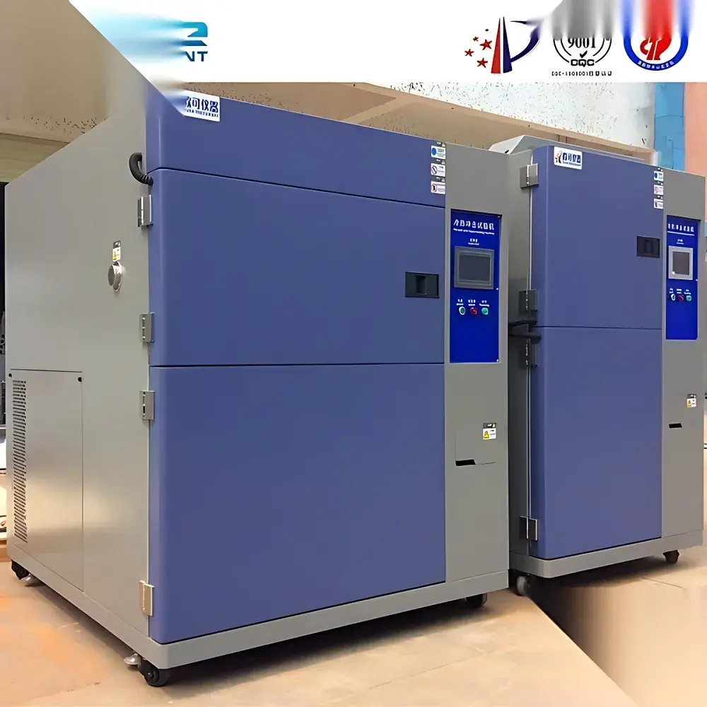
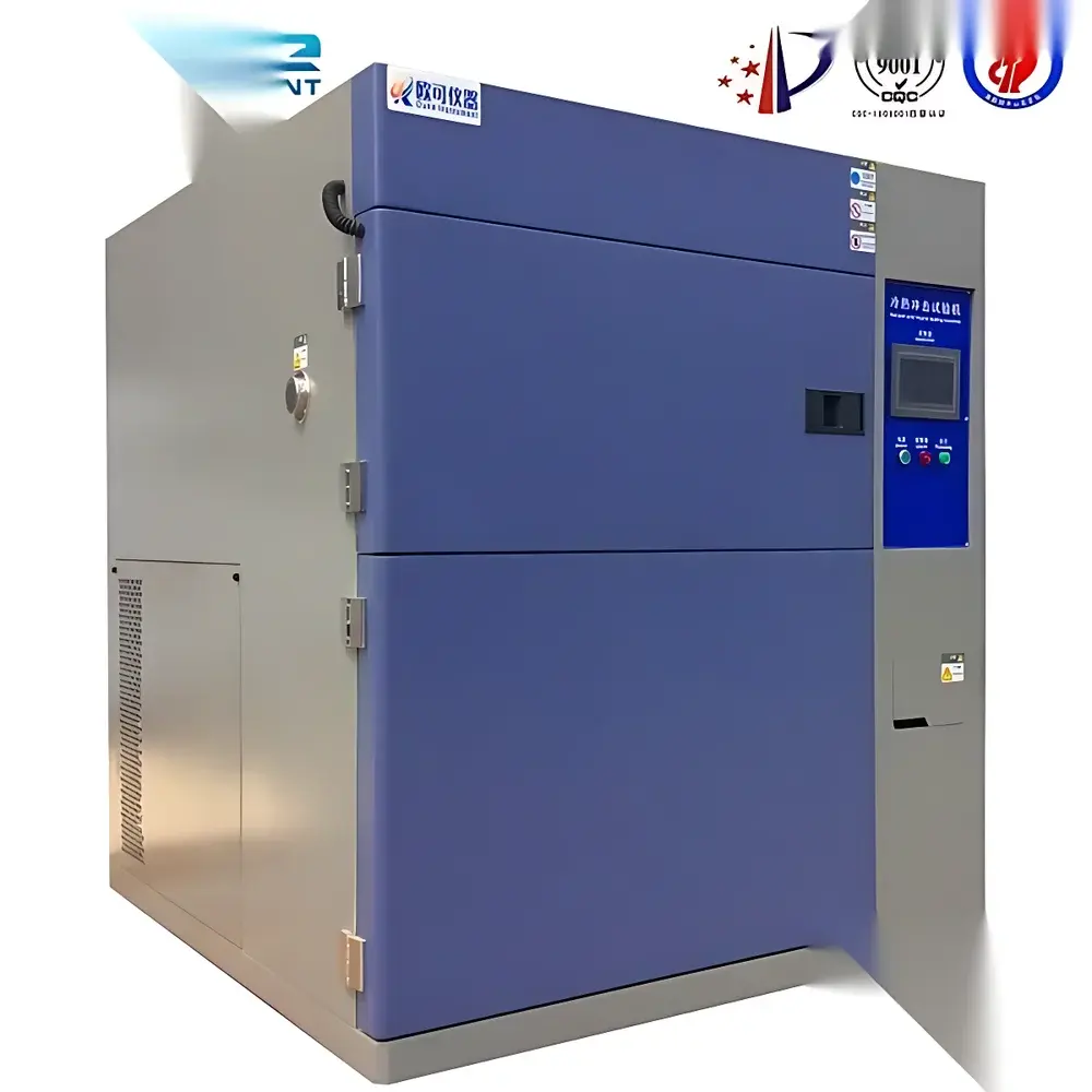
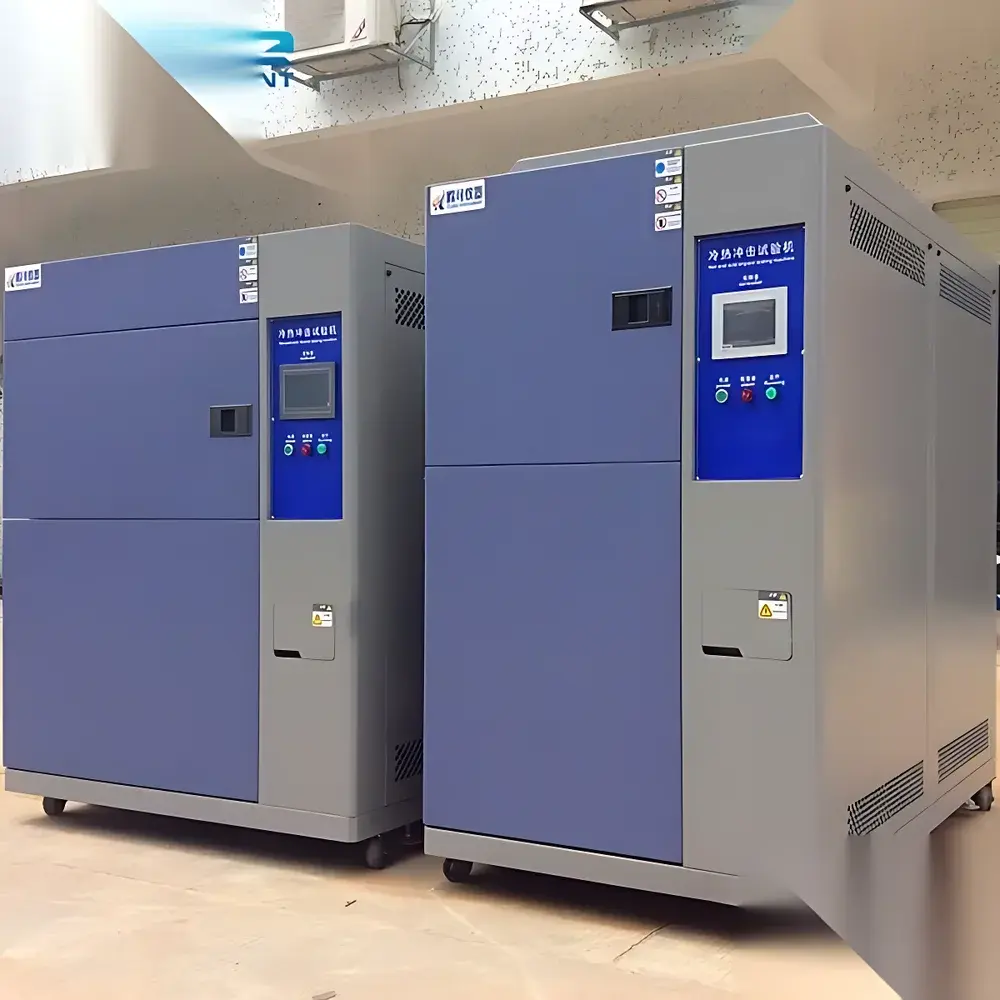
Three-Zone Thermal Shock Test Chamber
| Key Features | Three-zone design (hot zone, cold zone, test zone) |
|---|---|
| Temperature Range | Hot Zone: +80°C to +200°C |
| Cold Zone | −10°C to −70°C |
| Test Zone Operating Range | −10°C to +150°C |
| Temperature Control Accuracy | ±2°C |
| Resolution | 0.1°C |
| Hot Zone Ramp Rate | ~60 min (from ambient to +150°C) |
| Cold Zone Ramp Rate | ~120 min (from ambient to −60°C) |
| Test Zone Recovery Time | ≤3 min (with standard 2 kg I.C. load) |
| Internal Dimensions (Test Zone) | 500 × 350 × 500 mm (W×H×D) |
| External Dimensions | Approx. 1600 × 2050 × 2220 mm (W×H×D) |
| Construction | SUS304 stainless steel interior |
| Exterior | High-tensile cold-rolled steel with solvent-free powder coating |
| Insulation | Fire-retardant PU foam + glass wool, 100 mm thick |
| Compliance | GB10592–1989, GB2423.1, GB2423.2, GJB150.3, GJB150.4, IEC 60068-2-14, MIL-STD-810G |
Overview
The Three-Zone Thermal Shock Test Chamber is an engineered environmental simulation system designed for accelerated reliability evaluation of industrial components and materials under rapid, repetitive thermal transitions. Unlike single- or dual-chamber thermal shock systems, this three-zone architecture physically separates the high-temperature reservoir, low-temperature reservoir, and test chamber—enabling true zero-load thermal inertia during transfer and eliminating cross-contamination of thermal mass. The device operates on the principle of pneumatic-driven damper-controlled air transfer: test specimens remain stationary in the central test zone while thermally conditioned air from either reservoir is precisely directed via servo-actuated dampers, achieving thermal shock profiles compliant with IEC 60068-2-14 and MIL-STD-810G Method 503.5. This configuration ensures repeatable, traceable, and metrologically stable thermal transients—critical for qualifying electronic assemblies, aerospace fasteners, automotive sensors, and polymer-based enclosures subjected to field service conditions involving extreme ambient cycling.
Key Features
- Three independent thermal zones: dedicated hot reservoir (+80°C to +200°C), cold reservoir (−10°C to −70°C), and isolated test chamber (−10°C to +150°C)
- Pneumatic damper actuation system enabling <3-minute temperature recovery time in the test zone (per GB10592–1989, with 2 kg inertial load)
- High-resolution digital temperature control with ±2°C uniformity and 0.1°C display resolution
- SUS304 stainless steel inner chamber walls and floor; corrosion-resistant, non-outgassing construction suitable for cleanroom-adjacent operation
- 100 mm composite insulation layer comprising fire-rated polyurethane foam and high-density glass wool—meeting UL94 V-0 flame retardancy requirements
- Integrated anti-sweat heating circuit using K-type thermocouple feedback and microprocessor-based PID modulation to prevent condensation on structural interfaces
- Two adjustable stainless steel test trays (35 mm vertical pitch), heavy-duty casters with leveling feet, and precision damper positioning hardware to suppress turbulent mixing during thermal transfer
Sample Compatibility & Compliance
This chamber accommodates test specimens up to 500 mm (W) × 350 mm (H) × 500 mm (D) in volume and is routinely deployed for qualification testing of PCBAs, semiconductor packages, battery modules, optical housings, and elastomeric seals. Its mechanical and thermal performance conforms to national and international standards including GB2423.1 (cold testing), GB2423.2 (dry heat), GJB150.3A/150.4A (military environmental engineering), IEC 60068-2-14 (change of temperature), and MIL-STD-810G Method 503.5 (temperature shock). All thermal profiles are reproducible within defined uncertainty bands per ISO/IEC 17025-accredited calibration practices. The unit supports GLP-compliant test execution when paired with external data loggers meeting FDA 21 CFR Part 11 audit-trail requirements.
Software & Data Management
The chamber integrates a programmable logic controller (PLC) with real-time Ethernet interface (Modbus TCP) for remote monitoring and profile sequencing. While the base configuration includes a front-panel touchscreen HMI for manual operation and cycle definition, optional software packages support automated test script generation, multi-step thermal shock sequences (e.g., 100-cycle dwell-and-transfer protocols), and CSV-exportable temperature/time logs timestamped to UTC. Data integrity safeguards include cyclic redundancy check (CRC) validation on stored profiles and write-protected firmware partitions. For regulated environments, third-party SCADA integration enables full traceability—including operator ID, parameter lockout status, and deviation alerts—with audit trail generation aligned to Annex 11 and ALCOA+ principles.
Applications
- Qualification of solder joint integrity in automotive ECUs under repeated thermal cycling
- Evaluation of coefficient of thermal expansion (CTE) mismatch in multilayer ceramic capacitors (MLCCs)
- Validation of hermetic seal reliability in MEMS pressure sensors prior to field deployment
- Accelerated aging studies of aerospace-grade adhesives and potting compounds
- Pre-screening of lithium-ion battery cell housings for thermal runaway propagation resistance
- Verification of optical alignment stability in infrared lens assemblies across −55°C to +125°C excursions
FAQ
What distinguishes a three-zone thermal shock chamber from two-zone or single-chamber alternatives?
The physical separation of hot/cold reservoirs eliminates thermal lag during transfer cycles, enabling faster recovery times (<3 min), tighter temperature stability, and reduced compressor/heat exchanger wear over extended test durations.
Is the chamber suitable for testing samples containing moisture-sensitive components?
Yes—the anti-sweat heating system actively monitors and modulates surface temperatures at structural joints to prevent condensation ingress, and the sealed damper mechanism prevents humid ambient air from entering reservoir zones.
Can custom thermal shock profiles be programmed and validated?
Absolutely. Up to 99 multi-segment profiles can be stored locally, each supporting variable dwell times, ramp rates, and cycle counts; profile verification reports include thermocouple channel timestamps and deviation flags per ISO 17025 traceable calibration certificates.
Does the system support integration into an existing laboratory LIMS or MES platform?
Yes—via standard Modbus TCP or optional OPC UA gateway, enabling bi-directional command/control and automated result ingestion into enterprise quality management systems.
What maintenance intervals are recommended for long-term operational reliability?
Compressor oil and refrigerant filter replacement every 24 months; damper actuator lubrication and sensor calibration annually; full thermal mapping and uniformity verification per ISO/IEC 17025 every 12 months.


")