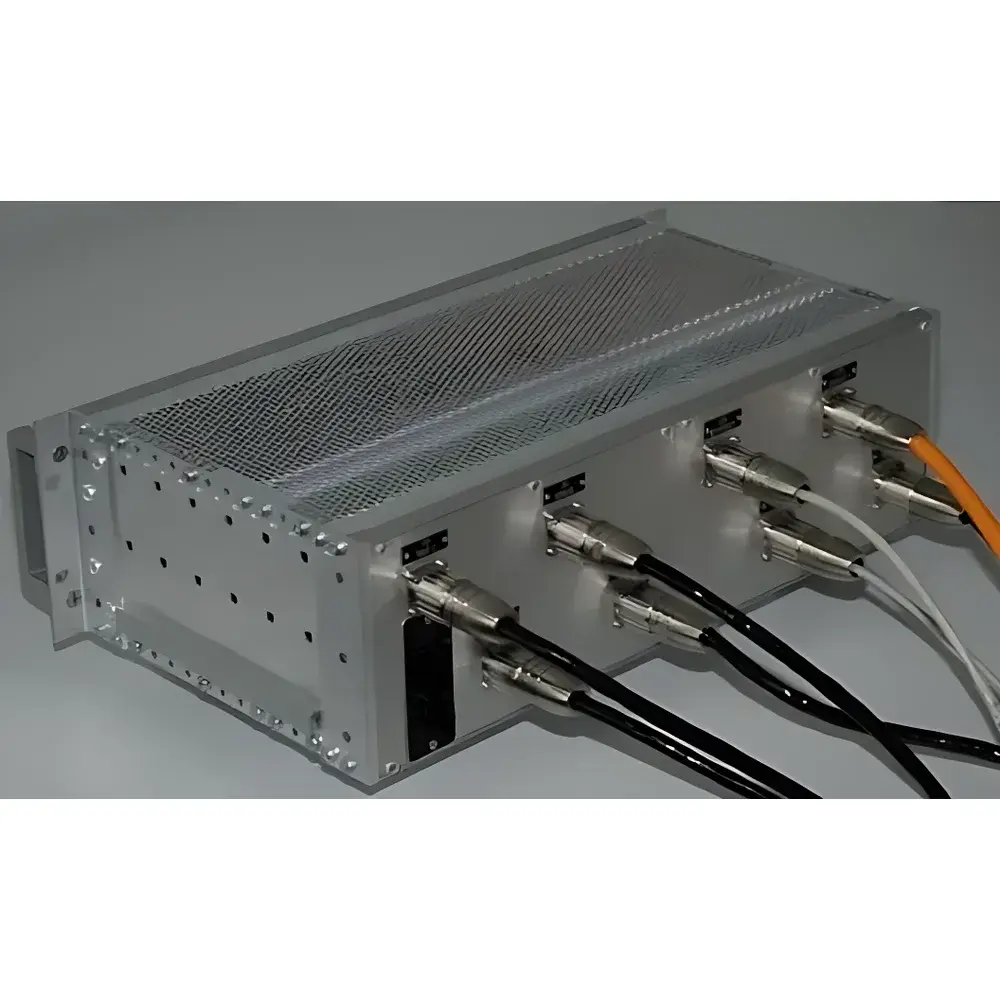
GeoSIG STS Seismic Trip System (Earthquake Switch)
| Brand | GeoSIG |
|---|---|
| Origin | Switzerland |
| Model | STS Seismic Trip System |
| Instrument Type | Portable |
| Mounting | 19″ Rack-Mountable Module |
| Compliance | Designed for IEC 61508 SIL 2-capable safety functions (per system integration) |
| Sensor Interface | Analog ±5 V or ±10 V differential outputs from GeoSIG accelerometers (e.g., GS-11, GS-13, CR-6plus-compatible) |
| Alarm Outputs | Relay contacts (SPDT, rated 250 VAC / 5 A resistive), galvanically isolated |
| Data Storage | Internal buffered memory (≥7 days continuous 100 Hz waveform at 24-bit resolution) |
| Communication | Ethernet (TCP/IP, Modbus TCP), RS-232/485 (Modbus RTU), optional SNMP support |
| Operating Temperature | −20 °C to +60 °C |
| Enclosure | 19″ 1U rack chassis, IP20 |
Overview
The GeoSIG STS Seismic Trip System is a purpose-engineered, rack-mounted seismic safety controller designed for automatic shutdown activation in critical infrastructure upon detection of earthquake-induced ground motion exceeding predefined acceleration thresholds. Operating on the principle of real-time analog signal conditioning combined with deterministic hardware-based trip logic, the STS delivers fail-safe, low-latency tripping functionality independent of software execution cycles—ensuring compliance with functional safety requirements for Safety Instrumented Systems (SIS). The system integrates seamlessly with field-validated GeoSIG accelerometers (e.g., GS-11, GS-13, CR-6plus series) via shielded differential analog inputs, enabling tripping based on single-axis, multi-axis vector magnitude, or user-defined composite criteria. Unlike purely software-driven alarm systems, the STS employs dedicated analog comparators and hardened relay drivers to generate certified alarm outputs within ≤20 ms of threshold breach—making it suitable for deployment in nuclear facilities, power plants, LNG terminals, and industrial process control environments where deterministic response time and hardware-level reliability are non-negotiable.
Key Features
- Hardware-determined trip logic: Critical alarm outputs generated exclusively by analog comparator circuits and solid-state relays—eliminating software boot delays, OS dependencies, or firmware update risks.
- Multi-axis triggering flexibility: Configurable trip conditions across individual X/Y/Z axes or Euclidean vector sum (SRSS), supporting both ISO 27888 and IEEE 693-compliant tripping strategies.
- Programmable analog filtering: Onboard 4th-order Bessel or Butterworth anti-aliasing filters (0.1–50 Hz selectable cutoff) ensure spectral integrity prior to digitization and trip decision.
- Full-waveform digital recording: Continuous 24-bit, 100 Hz sampling stored in circular buffer (≥7 days retention); supports post-event replay, spectral analysis, and shock response spectrum (SRS) computation.
- Comprehensive diagnostics & traceability: Real-time LED status indicators per channel, built-in test points for loop verification, mechanical key switch for maintenance mode, and full system event logging with UTC timestamping.
- Standardized integration architecture: 19″ 1U enclosure compliant with EIA-310-D; communication via Modbus TCP/RTU and Ethernet for SCADA/HMI interoperability; supports SNMP v2c/v3 for network monitoring.
Sample Compatibility & Compliance
The STS is validated for use with GeoSIG’s field-proven seismic sensors—including the GS-11 (±2 g, low-noise MEMS), GS-13 (±4 g, high-dynamic-range piezoelectric), and CR-6plus-series strong-motion accelerometers. All sensor interfaces adhere to IEEE 1350-1999 analog output standards. While the STS itself is not SIL-certified as a standalone device, its architecture enables integration into SIL 2–compliant Safety Instrumented Functions (SIFs) when deployed per IEC 61508 Part 3 guidelines and verified within the broader safety lifecycle. It meets EMC requirements per EN 61326-1 (industrial environment) and environmental robustness per IEC 60068-2 for operational temperature (−20 °C to +60 °C) and vibration resistance (IEC 60068-2-6, 5–500 Hz, 1.5 mm peak-to-peak).
Software & Data Management
Digital data acquisition and archival are managed through GeoSIG’s proprietary GeoNet Manager software suite—compatible with Windows 10/11 and supporting secure remote access via TLS 1.2. The software provides waveform visualization, configurable alarm threshold mapping, automated report generation (PDF/CSV), and audit-trail-enabled configuration change logging compliant with FDA 21 CFR Part 11 principles (electronic signatures, operation history, and user role-based permissions). Raw binary data is stored in standard SEED MiniSEED format, ensuring long-term readability and compatibility with third-party seismic processing tools (e.g., ObsPy, SAC, SeisComP). Scheduled data exports and email alerts for storage nearing capacity or communication loss are configurable without requiring local operator intervention.
Applications
- Automatic Seismic Trip Systems (ASTS) for nuclear reactor scram initiation and turbine emergency shutdown
- Emergency shutdown triggers in fossil-fuel and hydroelectric power generation facilities
- Process isolation in petrochemical refineries, LNG storage tanks, and hydrogen production units
- Seismic interlocks for overhead cranes, elevators, and automated material handling systems in earthquake-prone zones
- Structural health monitoring (SHM) backbone for bridges, dams, and high-rise buildings—providing both safety-critical tripping and long-term vibration trend analysis
FAQ
Does the STS require periodic calibration to maintain trip reliability?
Yes. While the hardware trip path is inherently stable, annual verification of sensor-to-relay chain performance—including sensitivity, frequency response, and threshold accuracy—is recommended per ISO 16063-31 and plant-specific QA procedures.
Can the STS operate autonomously without network connectivity?
Yes. All trip decisions and relay actuation are fully autonomous and occur independently of Ethernet or serial communication status. Network interfaces serve only for monitoring, configuration, and data retrieval.
Is the internal data buffer encrypted or password-protected?
No encryption is applied to buffered waveforms; however, access to data export and configuration requires authenticated login via GeoNet Manager with role-based privileges. Physical security of the rack-mounted unit remains the responsibility of the facility.
What is the maximum supported cable length between the STS and accelerometer?
Up to 300 m using twisted-pair shielded cable (e.g., Belden 8761) with proper grounding at the STS end—verified under EMI conditions per EN 61000-4-3 testing.
Does the STS support integration with DCS or PLC systems via hardwired dry contacts?
Yes. The SPDT relay outputs are rated for direct connection to DCS input cards, PLC safety modules, or emergency stop circuits without additional interface hardware.
Related Products