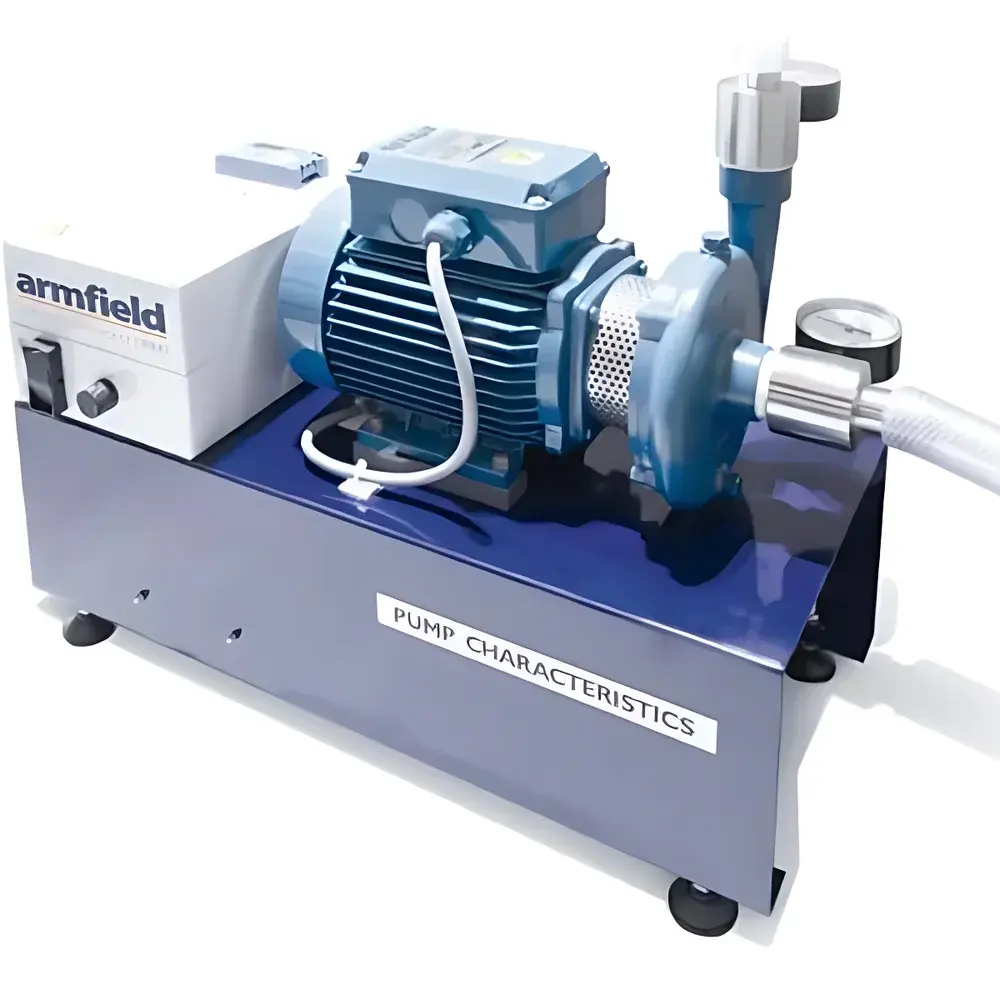
Armfield F1-27 Centrifugal Pump Characterization Demonstration Unit
| Brand | Armfield |
|---|---|
| Origin | United Kingdom |
| Model | F1-27 |
| Drive | Inverter-controlled AC motor |
| Pump Speed Range | 0–3000 rpm (adjustable) |
| Pressure Measurement | Inlet compound gauge, outlet pressure gauge, discharge manifold pressure gauge |
| Flow Control | Adjustable valve integrated into discharge manifold |
| Mounting | Floor-standing base with leveling feet |
| Compatibility | Designed exclusively for integration with Armfield F1-10 / F1-10-2 Hydraulic Bench |
| Interconnection | Quick-release flexible hoses for series or parallel configuration |
| Optional | Educational software package for data acquisition and pump performance curve generation |
| Compliance | CE-marked |
Overview
The Armfield F1-27 Centrifugal Pump Characterization Demonstration Unit is an engineered educational apparatus designed to provide hands-on, quantitative investigation of centrifugal pump performance under controlled hydraulic conditions. It operates on the fundamental principle of converting rotational mechanical energy—delivered by a precisely regulated induction motor—into fluid kinetic and potential energy via impeller-driven flow. The unit is not a standalone pumping system but a purpose-built auxiliary module intended for seamless integration with the Armfield F1-10 or F1-10-2 Hydraulic Bench, enabling rigorous experimental analysis of head–flow (H–Q), efficiency–flow (η–Q), and power–flow (P–Q) relationships in accordance with standard hydraulic testing methodology (ISO 5198, ASTM D1621). Its architecture supports both steady-state and transient characterization, allowing students and instructors to observe cavitation onset, throttling effects, and affinity law behavior across variable speed operation.
Key Features
- Inverter-driven AC motor with digital speed control (0–3000 rpm), offering continuous, stepless adjustment of rotational speed while maintaining torque stability across the operating range.
- Dual-point pressure monitoring: a compound pressure/vacuum gauge at the pump suction inlet and a calibrated pressure gauge at the discharge outlet—enabling direct measurement of differential head.
- Dedicated discharge manifold incorporating an adjustable flow control valve and an additional pressure gauge upstream of the diffuser, facilitating precise regulation and localized pressure assessment during throttling experiments.
- Modular quick-release hose connections using industrial-grade flexible tubing, permitting rapid reconfiguration for series or parallel pump arrangements with the base hydraulic bench or other compatible modules (e.g., F1-15, F1-21).
- Sturdy floor-standing support base with four independently adjustable leveling feet, ensuring mechanical stability and alignment integrity during dynamic load conditions—even when mounted adjacent to the F1-10 bench.
- Real-time electrical parameter display on the inverter interface: motor speed (rpm), output voltage (V), and motor current (A), supporting simultaneous mechanical and electromechanical performance correlation.
Sample Compatibility & Compliance
The F1-27 is validated for use with clean water within standard laboratory temperature ranges (5–35 °C) and atmospheric pressure conditions. It is not rated for abrasive, corrosive, or viscous fluids beyond ISO VG 32 mineral oil equivalents. All wetted components—including brass pressure ports, stainless steel shaft, and nitrile-sealed impeller—are selected for durability and compatibility with pedagogical hydraulic fluids. The unit complies with CE marking requirements under the EU Machinery Directive 2006/42/EC and Electromagnetic Compatibility Directive 2014/30/EU. Its design adheres to BS EN ISO 12100:2010 risk assessment principles and incorporates safeguarding features such as IP54-rated motor housing and non-slip base feet. Documentation includes full conformity declarations and traceable calibration certificates for all fitted gauges.
Software & Data Management
An optional educational software suite—compatible with Windows 10/11—is available for automated data logging, real-time graphing, and pump curve synthesis. The software interfaces via USB-to-RS485 converter to acquire synchronized readings from the inverter (speed, voltage, current) and external sensors (pressure, flow via optional F1-20 flowmeter). It generates exportable CSV datasets and pre-formatted lab reports compliant with UK university engineering curriculum frameworks (e.g., IET Accreditation criteria). Audit-trail functionality records user sessions, timestamped measurements, and configuration changes—supporting GLP-aligned teaching practices where traceability and reproducibility are emphasized.
Applications
- Experimental validation of pump affinity laws (N₁/N₂ = Q₁/Q₂ = √(H₁/H₂) = (P₁/P₂)^(1/3)).
- Construction and interpretation of characteristic curves: total head vs. flow rate, brake horsepower vs. flow, and hydraulic efficiency vs. flow.
- Analysis of system curve interaction and operating point determination in single- and multi-pump configurations.
- Observation of net positive suction head (NPSH) requirements and incipient cavitation signatures under variable suction pressure.
- Quantitative study of throttling losses, diffuser effectiveness, and energy conversion inefficiencies across Reynolds number regimes typical of centrifugal pump operation (Re > 1×10⁵).
- Integration into broader fluid mechanics coursework covering Bernoulli’s equation, continuity, and pipe network analysis.
FAQ
Is the F1-27 compatible with hydraulic benches other than the Armfield F1-10/F1-10-2?
No—the unit’s mounting geometry, pressure port locations, and hose interface specifications are engineered exclusively for interoperability with the F1-10 series. Adapters or custom manifolds are not supplied or supported.
Can the F1-27 be used for long-term continuous operation?
It is rated for instructional duty cycles only (maximum 2 hours per session, with ≥30-minute cooldown between runs) and is not certified for industrial 24/7 service.
Does the optional software support third-party sensor inputs?
Yes—via configurable analog input channels (0–10 V or 4–20 mA), provided signal conditioning and isolation meet IEC 61000-4-5 surge immunity requirements.
Are calibration certificates included with pressure gauges?
Yes—each gauge is supplied with a UKAS-accredited calibration certificate valid for 12 months from date of dispatch.
What maintenance is required between laboratory sessions?
Visual inspection of hose integrity, verification of leak-free connections, and periodic cleaning of the diffuser and valve seat with deionized water—no lubrication or disassembly is recommended.