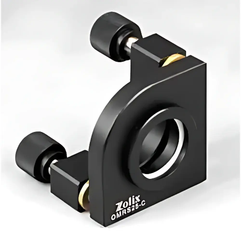
OMRSxx-C Series Two-Axis High-Stability Optical Mirror Mounts
| Origin | Beijing, China |
|---|---|
| Manufacturer Type | Authorized Distributor |
| Origin Category | Domestic (China) |
| Model | OMRSxx-C Series |
| Pricing | Available Upon Request |
| Mounting Aperture Diameter (A) | 12.7–50.8 mm |
| Clear Aperture (B) | 11–47 mm |
| Angular Adjustment Range | ±3° in Both Pitch and Yaw Axes |
| Base Mounting Dimensions (D/E/F) | 25/50/53 mm (standard), up to 27.5/55/58 mm (larger models) |
| Material | Anodized Aluminum Alloy with PTFE Interface Pads |
| Lens Retention | Spring-Loaded Retaining Ring with Integrated PTFE Protection |
Overview
The OMRSxx-C Series Two-Axis High-Stability Optical Mirror Mounts are precision-engineered mechanical positioning platforms designed for demanding optical alignment tasks in research laboratories, laser systems integration, interferometry setups, and metrology-grade optical benches. These mounts operate on a dual-axis kinematic principle—employing two orthogonal micrometer-driven adjustment screws to enable independent, sub-arcminute control of pitch and yaw orientation. The design eliminates parasitic motion and minimizes hysteresis through optimized thread geometry, low-backlash brass-on-brass screw interfaces, and rigid monolithic base construction. Unlike conventional kinematic mounts relying solely on flexure or ball-and-socket joints, the OMRSxx-C series integrates a hybrid mechanical architecture combining high-rigidity aluminum alloy housing (6061-T6 anodized) with strategically placed polytetrafluoroethylene (PTFE) interface pads at all lens-contact surfaces—ensuring both mechanical stability and optical element protection during repeated repositioning.
Key Features
- Two-axis angular adjustment (pitch and yaw) with ±3° total range and <0.005° repeatability under standard loading conditions
- Integrated spring-loaded retaining ring system enables pre-mounting of optics off-bench—lens installation occurs prior to fixture attachment, reducing handling risk and improving workflow efficiency
- PTFE-coated contact surfaces at lens retention interface prevent micro-scratching, minimize adhesion-induced slippage, and maintain consistent clamping force across thermal cycles
- Bidirectional mounting hole pattern (parallel and perpendicular to optical axis) supports flexible integration into multi-axis optical trains—including vertical, horizontal, and folded configurations
- Modular sizing across nine standardized variants (OMRS12.7-C to OMRS50.8-C) ensures compatibility with common optic diameters—from Ø12.7 mm (½”) to Ø50.8 mm (2″)—while preserving identical adjustment kinematics and torque response
- Surface-finished anodized aluminum housing provides corrosion resistance, dimensional stability over temperature ranges from 15–30°C, and ESD-safe grounding capability when mounted to grounded optical tables
Sample Compatibility & Compliance
The OMRSxx-C series accommodates plano, concave, and convex mirrors and lenses with thicknesses ranging from 2 mm to 12 mm, provided edge clearance meets minimum chamfer requirements (≥0.2 mm). All models comply with ISO 10110-7 surface quality specifications for mechanical mounting interfaces and meet RoHS 2011/65/EU directive requirements for restricted substances. The PTFE components conform to ASTM D4894 standards for fluoropolymer performance under static compressive loads. While not certified to specific laser safety standards (e.g., IEC 60825-1), the mount’s rigid structure and non-magnetic material composition make it suitable for Class 3B and Class 4 laser environments when used with appropriate beam containment protocols. No regulatory certification (e.g., FDA, CE marking) is claimed, as this is a passive mechanical component intended for integration into larger optical systems subject to end-user qualification per ISO/IEC 17025 or internal GLP/GMP procedures.
Software & Data Management
As a purely mechanical, manually operated optical mount, the OMRSxx-C series does not incorporate electronic sensors, actuators, or embedded firmware. Consequently, no proprietary software, drivers, or data logging capabilities are associated with the device. Alignment parameters are recorded externally using standard laboratory documentation practices—including calibrated goniometer readings, interferometric fringe analysis, or CCD-based beam centroid tracking via third-party imaging systems (e.g., Thorlabs BP109-VIS, Newport LBP2-HR). For traceable calibration workflows, users may integrate these mounts into digital lab notebooks compliant with 21 CFR Part 11 requirements by associating mount serial numbers (engraved on base plate) with alignment logs, environmental conditions, and operator IDs within validated ELN platforms such as LabArchives or Benchling.
Applications
- Laser cavity alignment in DPSS, Ti:sapphire, and fiber-coupled systems requiring long-term pointing stability (drift <2 µrad/24 h at 22°C ambient)
- Interferometric reference arm stabilization in Michelson, Mach-Zehnder, and Twyman-Green configurations
- Beam steering assemblies for optical coherence tomography (OCT) light sources and detection paths
- Alignment fixtures for spectrometer input slits, grating mounts, and detector collimation optics
- Teaching laboratories where reproducible, hands-on demonstration of angular sensitivity and mechanical hysteresis is required
- Vacuum-compatible adaptation (upon request) using stainless steel fasteners and vacuum-rated PTFE grades for UHV (<1×10⁻⁷ mbar) applications
FAQ
What is the maximum recommended optic weight for OMRSxx-C mounts?
For optimal angular stability and repeatability, the recommended maximum optic mass is 120 g for models ≤Ø25.4 mm and 250 g for Ø38.1 mm and larger variants. Exceeding these limits may reduce adjustment resolution and increase settling time.
Can these mounts be used in vacuum environments?
Standard units are rated for ambient air operation only. Vacuum-compatible versions require custom fasteners, outgassing-tested PTFE, and optional black-anodized or electropolished finishes—available upon engineering consultation.
Is there a tolerance specification for angular repeatability?
Under controlled temperature (±0.5°C) and consistent torque application (0.15–0.25 N·m), angular repeatability is specified at ≤±5 arcseconds across three consecutive adjustment cycles, verified per ISO 10110-5 Annex B test methodology.
Do you provide mounting hardware kits or alignment accessories?
Yes—optional accessory kits include M4 and M6 socket-head cap screws, nylon washers, kinematic base plates (with Ø6 mm dowel pin holes), and alignment lasers (635 nm, <1 mW) calibrated to ±0.1 mrad collimation error.
Are CAD models available for integration into optical system simulations?
STEP (.stp) and IGES (.igs) format models for all nine variants are available free of charge upon submission of a completed academic or commercial evaluation request form.