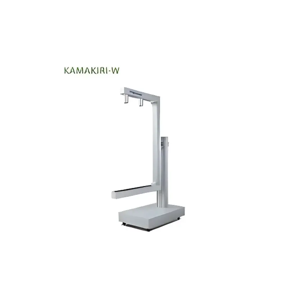
Photonic Lattice KAMAKIRI Online Birefringence Measurement System
| Brand | Photonic Lattice |
|---|---|
| Origin | Japan |
| Model | KAMAKIRI |
| Wavelength | 520 nm |
| Birefringence Range | 0–130 nm (standard), 0–260 nm (optional) |
| Fast Axis Orientation Range | 0–180° |
| Repeatability | <1 nm (σ) |
| Measurement Width | 350 mm |
| Spatial Resolution (Width Direction) | 2560 points |
| Output Parameters | Retardation [nm], Fast Axis Angle [°] |
Overview
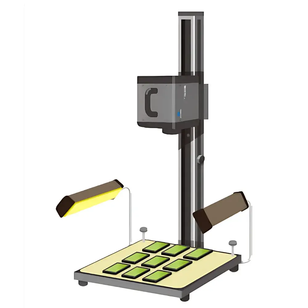
The Photonic Lattice KAMAKIRI Online Birefringence Measurement System is an industrial-grade, non-contact optical metrology instrument engineered for real-time, in-line birefringence characterization of transparent and semi-transparent polymer films, coated substrates, and molded optical components. Based on polarization-resolved imaging ellipsometry at a fixed wavelength of 520 nm, the KAMAKIRI system quantifies retardation (optical path difference) and fast-axis orientation across a 350 mm wide field of view with 2560 spatial sampling points. Unlike conventional benchtop retardation analyzers, the KAMAKIRI is designed for integration into continuous manufacturing environments—enabling closed-loop process monitoring of phase-difference films (e.g., TAC, PC, PMMA, COC), protective layers (PET, PEN, PS, PI), and precision-molded glass or resin optics. Its measurement principle relies on dual-channel polarization contrast imaging under controlled illumination, delivering high-speed, drift-free retardation maps without mechanical scanning or sample translation.
Key Features
- Real-time birefringence mapping at production line speeds—outputting retardation (nm) and fast-axis angle (°) continuously at user-defined frame rates
- High spatial fidelity: 2560 measurement points across 350 mm width, enabling detection of localized stress-induced anisotropy and coating uniformity defects
- Factory-calibrated repeatability of <1 nm (σ) under stable thermal and illumination conditions—validated per ISO 9001-compliant internal protocols
- Intuitive color-coded visualization interface: configurable hue-saturation-value (HSV) mapping for immediate OK/NG assessment of retardation distribution
- Configurable alarm logic: programmable thresholds for retardation magnitude and axis deviation, triggering visual/audio alerts and digital I/O signals upon anomaly detection
- Modular expansion capability: optional addition of auxiliary polarimetric sensors to increase lateral coverage or enable multi-wavelength validation (e.g., for dispersion analysis)
- Ruggedized industrial enclosure rated IP54, compatible with cleanroom Class 10,000 environments and standard PLC-based factory automation networks (EtherNet/IP, Modbus TCP)
Sample Compatibility & Compliance
The KAMAKIRI supports transmission-mode birefringence measurement of flat, optically homogeneous samples with thicknesses ranging from 25 µm to 3 mm and transmittance >60% at 520 nm. It is routinely deployed for quality assurance of cellulose triacetate (TAC), polycarbonate (PC), cyclo-olefin copolymer (COC), and poly(methyl methacrylate) (PMMA) phase compensation films; polyester (PET), polyethylene naphthalate (PEN), polystyrene (PS), and polyimide (PI) protective layers; and injection-molded optical lenses and cover glasses. The system complies with relevant portions of JIS K 7105 (optical properties of plastics), ASTM D882 (tensile properties of thin plastic sheeting—indirectly correlated to stress birefringence), and ISO 10110-5 (specification of optical elements—birefringence tolerancing). All calibration artifacts are traceable to NMIJ (National Metrology Institute of Japan) standards.
Software & Data Management
The KAMAKIRI operates with Photonic Lattice’s proprietary KAMAKIRI Control Suite v3.x—a Windows-based application supporting both operator-guided measurement and automated recipe-driven operation. Data output includes timestamped CSV files containing full 2560-point retardation and axis-angle vectors per acquisition cycle, as well as TIFF-encoded false-color maps compliant with FAIR data principles. The software provides built-in statistical process control (SPC) tools—including X-bar/R charts, histogram analysis, and trend tracking—with export compatibility to JMP, Minitab, and MES platforms via OPC UA. Audit trails, user access levels, and electronic signatures align with GLP and GMP documentation requirements; raw data integrity is preserved through SHA-256 hashing and write-once storage options meeting FDA 21 CFR Part 11 expectations for regulated industries.
Applications
- In-line monitoring of roll-to-roll (R2R) coating processes for retardation uniformity and edge effects
- End-of-line verification of optical film lamination stacks prior to cutting and packaging
- Process development support for thermoforming and injection molding of birefringence-sensitive optical components
- Root-cause analysis of warpage and residual stress in transparent polymer housings and display cover plates
- Qualification of substrate-level stress in semiconductor packaging films and flexible OLED encapsulation layers
- Comparative evaluation of annealing efficacy across different thermal treatment profiles
FAQ
What is the minimum measurable retardation value?
The system achieves sub-nanometer sensitivity in controlled lab environments; however, the practical lower limit in production settings is governed by optical noise floor and sample surface scatter—typically ~0.5 nm for high-quality TAC films.
Can the KAMAKIRI measure birefringence in curved or textured surfaces?
No—it is optimized for flat, smooth, transmission-mode samples. Curved or diffusely scattering surfaces require alternative techniques such as point-scanning Mueller matrix polarimetry.
Is spectral birefringence (wavelength-dependent retardation) supported?
Standard configuration operates at 520 nm only. Multi-wavelength extension requires integration of tunable LED sources and recalibration—available as a custom engineering option.
How is system calibration maintained during long-term operation?
A daily automated self-check routine verifies polarization channel balance and detector linearity using internal reference optics; full recalibration is recommended every 6 months or after mechanical shock events.
Does the system support integration with SCADA or MES platforms?
Yes—via native Modbus TCP and EtherNet/IP drivers, plus RESTful API endpoints for custom middleware integration and real-time dashboarding.