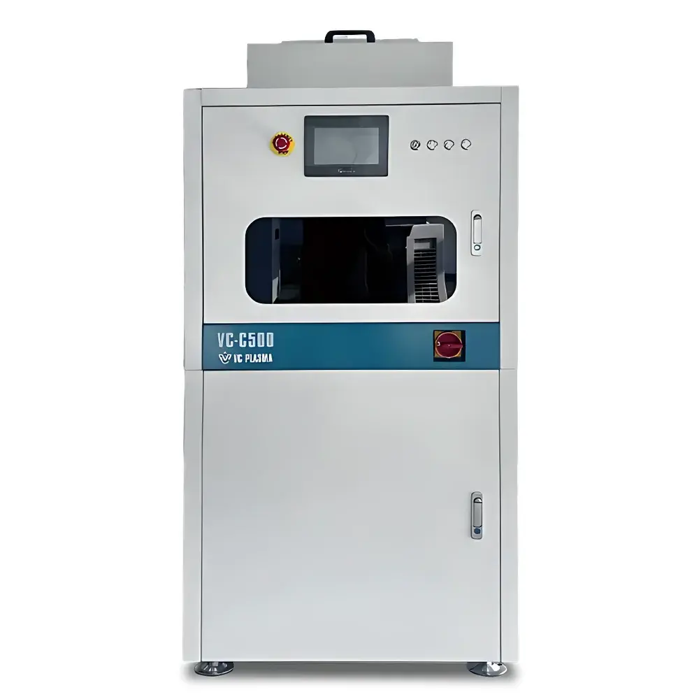
LEBO Science Customized-2 Benchtop Closed-Loop Wafer Developer
| Brand | LEBO Science |
|---|---|
| Origin | Imported |
| Manufacturer Type | Authorized Distributor |
| Model | Customized-2 |
| Wafer Compatibility | Fragments to 200 mm (customizable up to 300 mm with quad-nozzle configuration) |
| Development Modes | Single-step & Multi-step Programmable Process |
| Max. Spin Speed | 3000 rpm (no-load) |
| Speed Resolution | ±1 rpm |
| Acceleration Range | 10–10,000 rpm/sec (no-load) |
| Step Duration Range | 0–3000 sec |
| Time Resolution | 0.1 sec |
| Nozzle Control | Motorized XYZ-positioning with programmable trajectory |
| Fluid Delivery | 1 dedicated developer channel + 1 deionized water rinse channel + 1 N₂ purge channel |
| Compliance | Designed for Class 100–1000 cleanroom environments |
| Software | Onboard HMI with 100 user-editable process recipes |
Overview
The LEBO Science Customized-2 Benchtop Closed-Loop Wafer Developer is an engineered solution for precision photoresist development in R&D, pilot-line, and low-volume semiconductor fabrication environments. Based on controlled dispense-and-spin development methodology, the system implements a sequential process involving programmable chemical delivery, uniform resist dissolution under centrifugal force, timed solvent removal, and inert gas-assisted drying — all within a fully enclosed, particle-isolated chamber. Unlike open-batch developers, this closed-loop architecture minimizes airborne contamination, volatile organic compound (VOC) emissions, and cross-contamination between wafers, making it suitable for sub-micron lithography processes where feature fidelity and CD uniformity are critical. The system operates without integration into full track systems, enabling standalone evaluation of developer chemistry, post-exposure bake (PEB) interactions, and resist dissolution kinetics under reproducible mechanical conditions.
Key Features
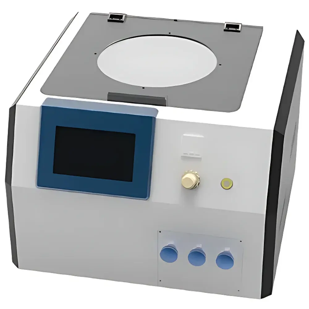
- Fully enclosed stainless-steel chamber with HEPA-filtered laminar airflow, rated for ISO Class 5 (Class 100) cleanroom compatibility.
- Motorized XYZ nozzle positioning system enables precise spatial control over developer dispense location — critical for edge-bead removal (EBR), center-in or edge-out dispense patterns, and non-uniform substrate geometries (e.g., broken wafers, test chips).
- Dual independent fluid manifolds: one chemically resistant PFA-lined channel for developer (e.g., TMAH, KOH, or organic solvents), and a separate DI-water channel with inline 0.1 µm filtration; both support pressure-regulated flow (0.5–4 bar) and real-time flow monitoring via integrated mass flow sensors.
- Nitrogen purge module with adjustable flow rate (0–30 L/min) and programmable activation timing ensures residue-free drying while suppressing oxidation of sensitive metal layers (e.g., Cu, Al).
- High-fidelity spin control: digital servo motor with encoder feedback delivers ±1 rpm speed resolution and acceleration ramping from 10 to 10,000 rpm/sec — essential for managing resist swelling, standing wave effects, and developer penetration depth during sub-100 nm patterning.
- Onboard touchscreen HMI with password-protected recipe management supports up to 100 editable multi-step programs, each configurable with independent parameters for dispense volume, dwell time, spin speed profile, acceleration ramp, and purge duration.
Sample Compatibility & Compliance
The Customized-2 accommodates substrates ranging from fragmented silicon pieces and SOI test dies to full 200 mm wafers; optional hardware upgrades extend compatibility to 300 mm wafers using reinforced chuck design and extended nozzle travel range. Chuck vacuum integrity is verified automatically prior to spin initiation (≥−75 kPa holding pressure). All wetted materials — including nozzles, fluid paths, and chamber liners — comply with SEMI F57 standards for semiconductor process equipment material compatibility. The system meets CE machinery directive (2006/42/EC) and RoHS 2 (2011/65/EU) requirements. Optional audit trail logging and electronic signature modules enable alignment with FDA 21 CFR Part 11 and ISO 9001:2015 quality management protocols for regulated development workflows.
Software & Data Management
Process data — including actual spin speed vs. setpoint, dispense volume per step, chamber temperature (±0.5 °C), and nitrogen pressure — are timestamped and stored locally in CSV format. USB export and optional Ethernet interface support integration with MES platforms (e.g., CIM300, FactoryTalk) via Modbus TCP. Recipe versioning, user access levels (Operator / Engineer / Admin), and change history logs satisfy GLP/GMP documentation requirements. Firmware updates are performed via secure signed package installation with rollback capability.
Applications
- Resist development optimization for EUV, DUV, and e-beam lithography processes.
- Characterization of developer concentration, temperature, and dispense strategy impact on line-edge roughness (LER) and linewidth variation (LV).
- Qualification of new resist formulations and post-lithography treatments (e.g., solvent vapor smoothing, thermal reflow).
- Failure analysis of pattern collapse, scumming, or footing defects through controlled parametric sweeps.
- Training and education in microfabrication labs where full-track exposure/development integration is impractical.
FAQ
Can the Customized-2 be integrated with a photolithography stepper or mask aligner?
Yes — optional I/O ports (dry contact, RS-232, and Ethernet) allow synchronized triggering with external exposure tools using TTL handshake signals.
Is ozone-resistant tubing available for aggressive developer chemistries?
Standard configurations use PFA and EPDM; fluorosilicone or Kalrez®-lined options are available upon request for TMAH >2.38% or high-pH aqueous solutions.
Does the system support temperature-controlled developer dispensing?
An optional heated fluid manifold (ambient to 45 °C, ±0.3 °C stability) is available for thermally sensitive resists requiring precise developer temperature control.
What maintenance intervals are recommended for the spin motor and vacuum pump?
Motor bearing inspection every 1,500 operating hours; vacuum pump oil replacement every 500 hours or quarterly — documented in the preventive maintenance logbook included with shipment.