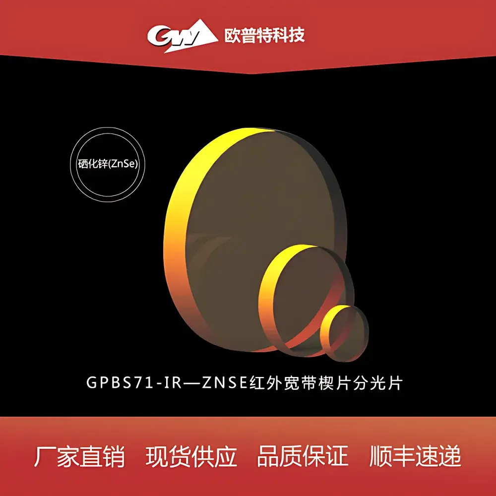
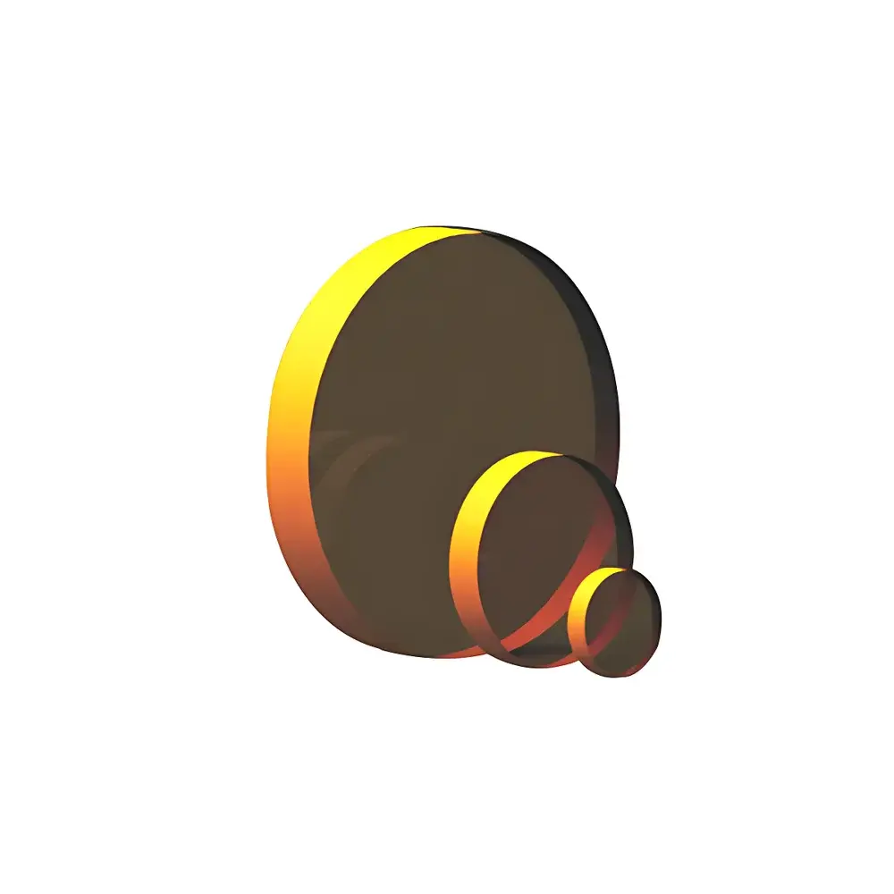
GPBS71 ZnSe Broadband Infrared Wedge Beam Splitter
| Material | ZnSe |
|---|---|
| Surface Flatness | λ/4 @ 633 nm |
| Wedge Angle | 30 arcmin ± 10 arcmin |
| Surface Quality | 3–4 scratch-dig |
| Clear Aperture | ≥90% |
| Diameter Tolerance | +0/−0.25 mm |
| Thickness Tolerance (Edge) | ±0.25 mm |
| Edge Treatment | Protective 45° chamfer, 0.2–0.5 mm |
| S1 Coating | Broadband R/T ≈ 70/30 ±10% avg. @ 7–14 µm, 45° AOI |
| S2 Coating | Broadband AR, Ravg < 2.5% @ 7–14 µm, 45° AOI |
Overview
The GPBS71 ZnSe Broadband Infrared Wedge Beam Splitter is a precision optical component engineered for stable, low-distortion beam division in mid-wave to long-wave infrared (MWIR–LWIR) systems operating from 7 to 14 µm. Unlike conventional flat plate beam splitters, the wedge geometry inherently suppresses ghost reflections and interference fringes between front- and back-surface reflections—critical for interferometric setups, FTIR spectrometers, thermal imaging calibration rigs, and CO₂ laser diagnostics. Constructed from high-purity zinc selenide (ZnSe), this component exhibits excellent transmission (>70% uncoated bulk) across its design band and minimal absorption-induced thermal lensing under moderate CW IR irradiance. The 30 arcminute wedge angle is tightly controlled (±10 arcmin) to ensure predictable beam deviation while maintaining collimation integrity in folded-path configurations.
Key Features
- Optimized ZnSe substrate with refractive index ~2.4 at 10.6 µm and low dispersion across 7–14 µm
- S1 face coated with durable, broadband metallic-dielectric hybrid thin-film stack delivering nominal 70R/30T split ratio at 45° angle of incidence, with ±10% uniformity across full spectral band
- S2 face featuring multi-layer dielectric anti-reflection coating achieving average reflectance <2.5% across 7–14 µm, minimizing residual etalon effects
- Surface flatness specified to λ/4 @ 633 nm (measured via HeNe interferometry), ensuring wavefront distortion <0.25 µm PV over clear aperture
- Surface quality rated 3–4 scratch-dig per MIL-PRF-13830B, validated by dark-field inspection under 50× magnification
- Protective 45° edge chamfer (0.2–0.5 mm) mitigates chipping during handling and mounting in kinematic or flexure-based mounts
- Clear aperture ≥90% of nominal diameter, supporting high-throughput alignment without vignetting in Ø12.7 mm, Ø25.4 mm, and Ø50.8 mm variants
Sample Compatibility & Compliance
The GPBS71 complies with standard optical manufacturing practices defined in ISO 10110-7 (surface imperfections) and ISO 10110-3 (surface form tolerances). Its ZnSe material meets ASTM F1625 specifications for infrared-transmitting optical grade semiconductors. Coating adhesion is verified per MIL-C-48497A (tape test, Class 5A). While not intrinsically certified for medical or aerospace deployment, the component satisfies baseline requirements for laboratory-grade IR instrumentation used in ISO/IEC 17025-accredited testing facilities. It is compatible with vacuum-compatible mounting hardware (e.g., Kinemetrics K-mounts) and exhibits no outgassing concerns per ASTM E595 when baked at ≤60°C prior to chamber insertion.
Software & Data Management
As a passive optical component, the GPBS71 requires no embedded firmware or driver software. However, its performance parameters are fully integrated into common optical design platforms—including Zemax OpticStudio (v23+), CODE V (v12.2+), and FRED—via supplied .DAT files containing measured refractive index (Sellmeier coefficients for ZnSe), coating spectral reflectance/transmittance curves (0°–45° AOI), and surface tolerance maps. All spectral data are traceable to NIST-calibrated FTIR measurements (Bruker Vertex 80v, resolution 0.5 cm⁻¹). Manufacturing lot documentation includes interferometric surface map reports (ASCII .ZMX format), coating spectrophotometry logs (.CSV), and dimensional inspection certificates compliant with ASME Y14.5-2018 GD&T standards.
Applications
- Reference arm splitting in Michelson and Mach–Zehnder interferometers for gas-phase spectroscopy (e.g., CH₄, CO, NO₂ detection)
- Beam sampling in industrial CO₂ laser power monitoring systems (10.6 µm), where thermal stability and low polarization dependence are essential
- Multi-channel thermal imaging alignment fixtures requiring simultaneous visible alignment and IR path validation
- Calibration sources for uncooled microbolometer arrays, leveraging consistent R/T ratio to define known radiant flux ratios
- Attenuated total reflection (ATR) accessory integration in portable FTIR analyzers, where wedge geometry minimizes internal reflection artifacts
- Low-coherence interferometry (LCI) systems operating in the fingerprint region (9–11 µm) for polymer characterization
FAQ
What is the typical damage threshold for the S1 coating under pulsed CO₂ laser exposure?
For 10.6 µm, 100 ns pulses at 10 Hz repetition rate, the LIDT is ≥0.5 J/cm² (tested per ISO 21254-2); continuous-wave operation is limited to ≤2 kW/cm² to avoid thermal delamination.
Can this wedge be used at angles other than 45° AOI?
Yes—spectral performance shifts predictably; R/T ratio increases to ~75/25 at 30° AOI and drops to ~65/35 at 60° AOI. Custom AOI optimization is available upon request.
Is the ZnSe substrate resistant to humidity or chemical exposure?
ZnSe is hygroscopic and susceptible to oxidation in high-humidity environments (>60% RH) or acidic vapors; operation in dry nitrogen purged enclosures or sealed housings is recommended for long-term stability.
Do you provide wavefront error measurement reports for individual units?
Yes—interferometric wavefront maps (Zernike coefficients up to 37th order) and PV/RMS values are included with each shipped unit upon request, with traceability to NPL UK interferometer calibration.
Are custom diameters or wedge angles available?
Standard offerings cover Ø12.7 mm, Ø25.4 mm, and Ø50.8 mm. Non-standard diameters (Ø6–Ø100 mm) and wedge angles (5–60 arcmin) are manufacturable under NRE agreement with 8–12 week lead time.