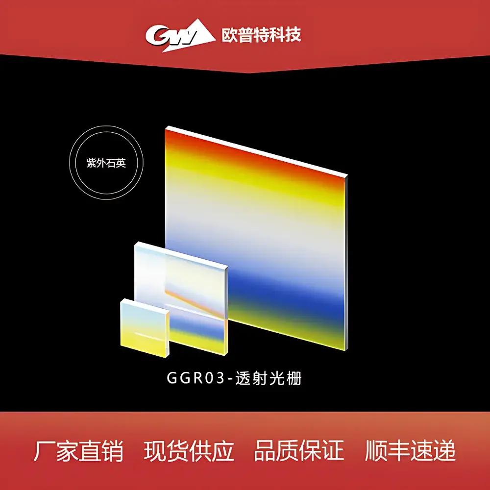
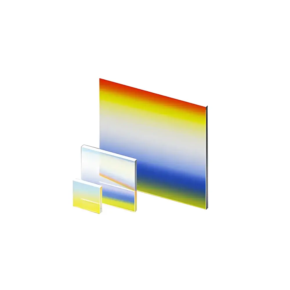
GGR03 Transmission Diffraction Grating
| Origin | Beijing, China |
|---|---|
| Manufacturer Type | Authorized Distributor |
| Product Origin | Domestic (China) |
| Model | GGR03 |
| Component Category | Optical Element |
| Price Range | USD 72–143 (based on size, groove density, and coating configuration) |
| Substrate Material Options | UV Fused Silica (for UV), BK7 / B270 (for VIS/NIR) |
| Available Sizes | 12.7×12.7×2 mm, 25×25×2 mm, 50×50×2 mm (UV) |
| Groove Densities | 300, 600, 830, 1200 l/mm |
| Blaze Wavelengths (VIS/NIR) | 270 nm, 532 nm, 780 nm, 1064 nm (configurable per order) |
| Diffraction Efficiency | Optimized for Littrow or non-Littrow mounting |
Overview
The GGR03 Transmission Diffraction Grating is a precision optical component engineered for high-fidelity spectral dispersion in compact, alignment-tolerant optical systems. Operating on the principle of constructive interference from periodic microstructures etched into optically homogeneous substrates, this grating enables linear wavelength separation across ultraviolet (UV), visible (VIS), and near-infrared (NIR) spectral regions. Unlike reflective gratings, transmission gratings simplify optical path design by eliminating the need for additional folding mirrors or complex beam re-routing—making them especially suitable for miniaturized spectrometers, OEM sensor modules, hyperspectral imaging engines, and fiber-coupled spectroscopic instrumentation. The GGR03 series features low wavefront distortion, minimal polarization dependence (<0.5% efficiency variation between s- and p-polarized input), and insensitivity to certain collimation errors inherent in low-cost collimating optics—thereby improving system robustness and reducing assembly tolerances during integration.
Key Features
- Multi-band substrate compatibility: UV-grade fused silica (for 190–400 nm), BK7/B270 optical glass (for 400–1100 nm), and custom NIR-optimized variants (up to 1700 nm)
- Precision holographic or ruled fabrication with controlled groove profile and blaze optimization for maximum diffraction efficiency in target spectral bands
- Standard groove densities: 300, 600, 830, and 1200 lines/mm—enabling trade-offs between angular dispersion, free spectral range, and resolution requirements
- High thermal and mechanical stability: Coefficient of thermal expansion (CTE) matched to common optical mounts; no adhesives or epoxy layers in the optical path
- AR-coated options available on both entrance and exit faces to minimize Fresnel losses—particularly critical for multi-pass or low-light applications
- Consistent surface flatness (λ/10 @ 633 nm) and scratch-dig specification of 20–10 per MIL-PRF-13830B
Sample Compatibility & Compliance
The GGR03 grating is compatible with standard optomechanical interfaces including SM1 (1.035″-40), C-mount, and custom flange configurations. All substrates comply with ISO 10110-7 surface quality standards and RoHS Directive 2011/65/EU for hazardous substance restrictions. For regulated environments—including clinical spectroscopy, pharmaceutical process analytical technology (PAT), and environmental monitoring—the grating supports traceable calibration documentation and can be supplied with individual test reports (including diffraction efficiency curves, wavefront error maps, and spectral responsivity data). While the component itself does not require FDA registration, its use in Class I or Class II diagnostic devices must conform to IEC 61000-4 electromagnetic compatibility standards and ISO 13485 quality management system requirements when integrated into medical hardware.
Software & Data Management
Although the GGR03 is a passive optical element, its performance parameters are fully embeddable into optical design software platforms including Zemax OpticStudio, CODE V, and FRED. Manufacturer-provided ZMX files and ASAP-compatible ray-splitting models are available upon request for accurate system-level simulation of dispersion, throughput, and stray light. For end-users developing spectral calibration workflows, diffraction angle vs. wavelength lookup tables (in CSV and JSON formats) are supplied with each batch, aligned to NIST-traceable reference lasers (e.g., HeCd 325 nm, HeNe 632.8 nm, Nd:YAG 1064 nm). These datasets support automated wavelength calibration routines compliant with ASTM E275-22 (Standard Practice for Calibration of Spectrophotometers) and enable GLP/GMP audit-ready documentation when paired with laboratory information management systems (LIMS).
Applications
- Miniature array-based spectrometers for handheld Raman and LIBS analyzers
- Wavelength division multiplexing (WDM) modules in telecom and datacom transceivers
- Monochromator-free fluorescence detection systems in flow cytometry and microplate readers
- UV-VIS-NIR process monitoring sensors for semiconductor thin-film deposition and chemical vapor synthesis
- Educational optics kits for undergraduate physics laboratories (e.g., resolving power measurement, angular dispersion verification)
- Space-qualified payloads requiring radiation-hardened transmission optics with low outgassing (upon request with ASTM E595 certification)
FAQ
What is the typical damage threshold for the GGR03 grating under CW laser illumination?
For uncoated UV fused silica substrates at 355 nm, the laser-induced damage threshold (LIDT) is ≥5 J/cm² (10 ns pulse, 10 Hz, Ø0.5 mm spot). AR-coated versions exhibit slightly reduced thresholds due to thin-film absorption; exact values depend on coating stack design and are provided in the Certificate of Conformance.
Can the GGR03 be used in vacuum or high-humidity environments?
Yes—standard versions meet ISO 9001 cleanroom assembly protocols and exhibit <0.01% mass loss in ASTM E595 outgassing tests. For sustained operation above 85% RH, optional hydrophobic SiO₂ overcoat is recommended to prevent moisture adsorption on groove surfaces.
Is custom groove density or blaze wavelength available?
Yes—custom holographic or ion-beam etched gratings with groove densities from 100–2400 l/mm and blaze wavelengths from 193 nm to 1550 nm are available under NRE-supported development contracts.
How is angular alignment tolerance quantified for the GGR03 in a collimated beam?
The grating exhibits ≤0.15° angular sensitivity to incident beam tilt (full-width half-maximum efficiency drop <5%) for groove densities ≤600 l/mm; tolerance decreases inversely with groove density, as verified per ISO 14132-3 imaging standard procedures.
Are mounting fixtures or kinematic adapters included with purchase?
No—mounting solutions are application-specific and sold separately. Standard recommendations include Thorlabs KM100 or Newport UMB125-12.5 kinematic mounts, or custom-designed holders with ±2 µm tip/tilt adjustability for fine spectral alignment.