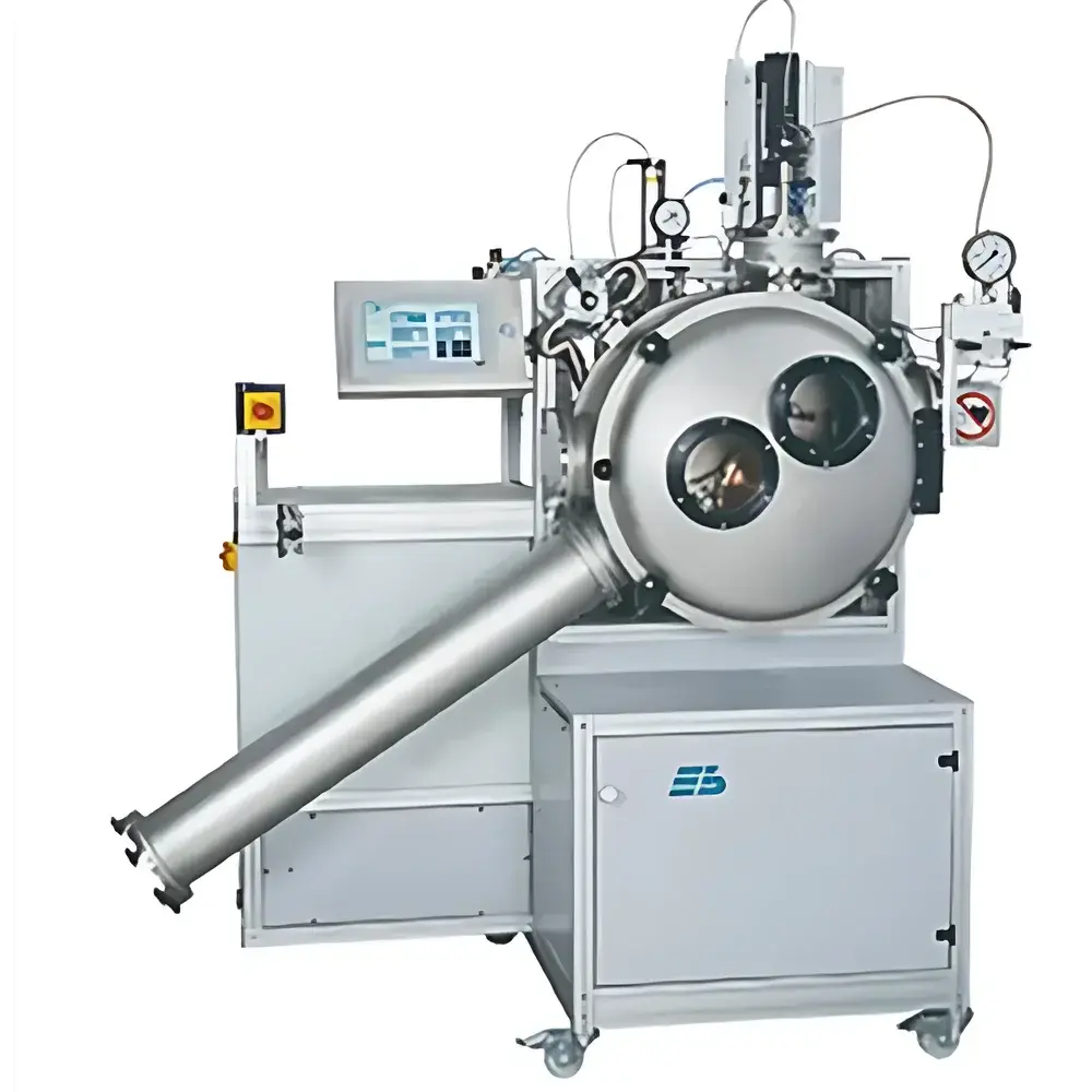
Edmund Bühler MSP 10 and MSP 60 Melt Spinning Systems
| Brand | Edmund Bühler |
|---|---|
| Origin | Germany |
| Model | MSP 10 and MSP 60 |
| Maximum Operating Temperature | up to 1500 °C |
| Vacuum Level | < 10⁻² – 10⁻⁵ mbar |
| Sample Capacity | 5–10 g (MSP 10), up to 60 g (MSP 60) |
| Copper Wheel Diameter | Ø200 mm (MSP 10), Ø250 mm (MSP 60) |
| Wheel Surface Velocity | up to 60 m/s (solid copper), 35 m/s (water-cooled copper) |
| Ribbon Width | 1–10 mm (MSP 10), 1–17 mm (MSP 60) |
| Ribbon Thickness | 20–60 µm |
| Cooling Rate | ~10⁵ K/s |
| RF Generator Power | 5–6 kW (MSP 10), 12–25 kW (MSP 60) |
| Crucible Materials | Boron nitride, quartz, or graphite |
| Power Supply | 400 V, 3-phase, 50/60 Hz (RF generator) |
Overview
The Edmund Bühler MSP 10 and MSP 60 are high-precision, vacuum-compatible melt spinning systems engineered for rapid solidification of metallic alloys and intermetallic compounds into amorphous or nanocrystalline ribbons. Based on the principle of planar flow casting (PFC), these instruments utilize electromagnetic induction heating (RF) to melt feedstock within a refractory crucible, followed by controlled ejection of molten material onto a high-speed rotating copper wheel under ultra-high vacuum or inert gas atmosphere. The resulting quenching rates—on the order of 10⁵ K/s—enable suppression of equilibrium phase formation, facilitating the synthesis of metastable phases, glass-forming alloys, and functional soft magnetic materials such as Fe-, Co-, and Ni-based ribbons. Both models operate in fully sealed stainless-steel vacuum chambers equipped with turbomolecular or diffusion pumping systems, ensuring oxygen-free processing critical for oxidation-sensitive compositions.
Key Features
- Integrated RF induction heating system with selectable power outputs: 5–6 kW (MSP 10) and 12–25 kW (MSP 60), enabling precise thermal control across diverse alloy systems including refractory and high-melting-point metals.
- Motor-driven, water-cooled copper wheels with diameters of Ø200 mm (MSP 10) and Ø250 mm (MSP 60); optional water-cooled wheel configuration available for MSP 60 to support extended operation at elevated thermal loads.
- Automated crucible positioning system (TPS) with dual-axis adjustment for reproducible alignment between nozzle exit and wheel surface—critical for consistent ribbon geometry and thickness uniformity.
- Touchscreen HMI control panel synchronizing real-time monitoring and actuation of RF generator current, wheel rotational speed, vacuum status, pyrometric temperature feedback, and automated polishing cycles.
- Modular chamber design featuring movable support frames, quick-access flanges, and standardized CF ports for integration of auxiliary diagnostics (e.g., in-situ X-ray diffraction, high-speed imaging).
- Dual-mode operational capability: standard melt-spinning mode and optional casting mode (MSP 60 only), where the copper wheel is replaced by a two-piece water-cooled copper mold for ingot or button casting under argon pressure.
Sample Compatibility & Compliance
The MSP series accommodates a broad spectrum of conductive feedstock materials—including elemental metals, master alloys, and pre-alloyed rods—with compatibility extending to boron nitride, quartz, and graphite crucibles rated for service temperatures up to 1700 °C (BN), 1200 °C (quartz), and >2000 °C (graphite). All vacuum components conform to DIN 28403 and ISO 286-2 dimensional tolerances; chamber integrity is validated per ISO 10816-3 vibration criteria and leak-tested to ≤1×10⁻⁹ mbar·L/s He. The systems support GLP-compliant workflows through configurable audit trails, user-level access control, and timestamped parameter logging—all traceable to IEC 62304 software lifecycle standards. Optional pyrometry integration meets ASTM E2847 requirements for non-contact temperature measurement in metallurgical processes.
Software & Data Management
Control firmware runs on a deterministic real-time OS with synchronized sampling of thermal, mechanical, and vacuum parameters at ≥1 kHz resolution. Process data—including melt duration, wheel velocity, RF power ramp profiles, and vacuum decay curves—are exported in HDF5 format for post-acquisition analysis in MATLAB, Python (NumPy/Pandas), or Thermo Scientific Avizo. The embedded historian supports 21 CFR Part 11–compliant electronic signatures when paired with validated identity management modules. Remote diagnostics via encrypted TLS 1.3 tunnel enables OEM-level troubleshooting without compromising network security protocols mandated by institutional IT policies.
Applications
- Synthesis of amorphous Fe78Si9B13, Co66Fe4Mo2Si16.7B11.3, and Nd-Fe-B precursor ribbons for permanent magnet development.
- Rapid prototyping of high-entropy alloy (HEA) compositions requiring extreme quenching kinetics to stabilize single-phase solid solutions.
- Production of ribbon stock for subsequent powder metallurgy routes—including jet milling, spark plasma sintering (SPS), and additive manufacturing feedstock qualification.
- Phase diagram refinement studies via systematic variation of wheel speed (10–60 m/s) and melt superheat (ΔT = 50–300 K) under controlled vacuum conditions.
- In-situ evaluation of melt viscosity and surface tension effects using slit-nozzle versus circular-nozzle configurations.
FAQ
What vacuum level is required for optimal amorphous ribbon formation?
Optimal results are achieved at base pressures ≤5×10⁻⁵ mbar, typically attained using a combination of roughing pump + turbomolecular pump. For reactive systems (e.g., Ti-, Zr-based alloys), cryogenic trapping may be added to suppress residual H₂O and O₂ partial pressures.
Can the MSP 60 produce wider ribbons than the MSP 10?
Yes—the MSP 60 supports ribbon widths up to 17 mm due to its larger Ø250 mm wheel and adjustable tilt mechanism that optimizes melt stream impingement angle relative to wheel curvature.
Is crucible alignment repeatable between runs?
Yes—the TPS (Tool Positioning System) provides motorized, encoder-feedback positioning with ±2 µm repeatability across both vertical and lateral axes, ensuring identical nozzle-to-wheel standoff distance across hundreds of sequential experiments.
What safety certifications do these systems carry?
All units comply with CE marking per Machinery Directive 2006/42/EC, EMC Directive 2014/30/EU, and Low Voltage Directive 2014/35/EU. RF shielding meets ICNIRP 2020 exposure limits for occupational environments.
How is ribbon thickness controlled?
Ribbon thickness is governed by a triad of parameters: melt temperature (affecting viscosity), wheel velocity (determining contact time), and nozzle geometry (slit width or orifice diameter). Empirical calibration curves are generated during initial commissioning for each alloy family.


