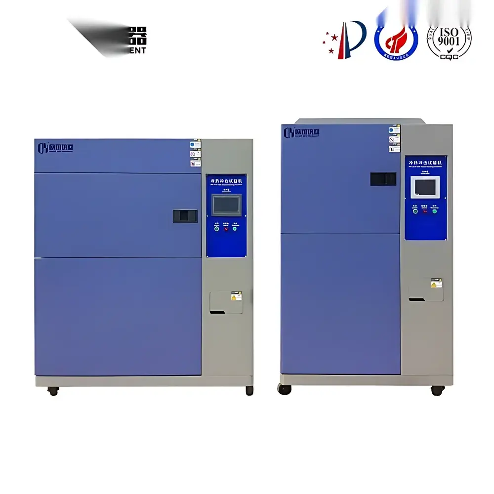
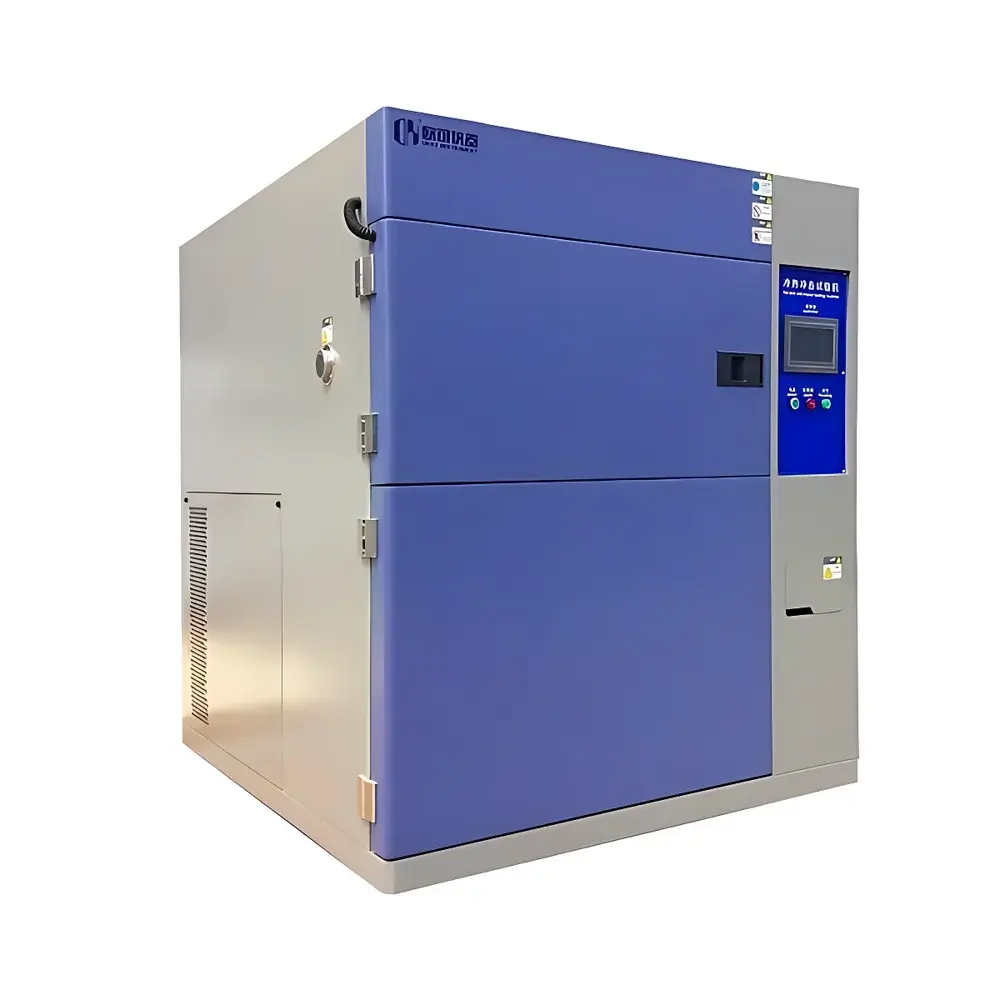
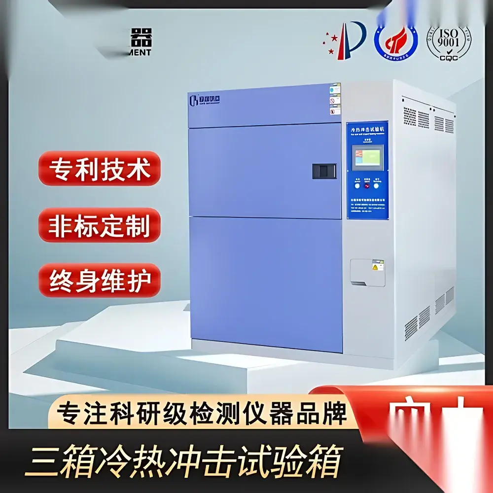
Thermal Shock Test Chamber – High-Temperature Cycling Environmental Chamber
| Brand | OEM / Custom-Built |
|---|---|
| Origin | Imported |
| Manufacturer Type | Authorized Distributor |
| Price | USD 11,200 (FOB) |
| Temperature Range | −70°C to +180°C (Standard Configuration) |
| Thermal Transition Rate | ≥10°C/min (Typical, 5–15°C/min configurable) |
| Internal Volume | 100 L / 225 L / 400 L / 800 L (Modular Options) |
| Control System | TEMI880 Color Touchscreen PLC Controller (EN/CN Switchable) or TEMI300 Membrane Keypad Controller (English Only) |
| Compliance | ISO 16750-4, MIL-STD-810H Method 503.5, IEC 60068-2-14, JIS Z 8702 |
| Refrigeration | Twin-Stage or Cascade Refrigeration System with Original Tecumseh/Tecumseh-derived or Copeland/Tecumseh “Tecumseh”-equivalent Hermetic Compressor |
| Insulation | High-Density Mineral Wool (≥100 mm Thickness) |
| Interior Material | SUS304B Stainless Steel, Full Argon-Shielded Welding |
| Air Circulation | Wide-Band Forced Convection via Centrifugal Blower + Axial Fans (Top-Out / Bottom-In Flow Pattern) |
| Humidity Control | Surface Evaporation Type Humidifier (Optional for Thermal-Humidity Shock Models) |
| Safety Protections | Compressor Overheat/Overcurrent/High-Pressure Cut-off, Dry-Heater Burnout Prevention, Chamber Over-Temperature Alarm, Low-Water-Level Detection, Door Interlock |
Overview
The Thermal Shock Test Chamber – High-Temperature Cycling Environmental Chamber is an engineered solution for accelerated reliability validation of electronic components, automotive ECUs, aerospace avionics, and high-performance materials under rapid, repetitive thermal transitions. Based on the principle of two-zone or three-zone thermal shock (air-to-air), the chamber alternates test specimens between independently controlled high-temperature and low-temperature zones—achieving temperature transition rates exceeding 10°C per minute. This replicates real-world operational stresses induced by thermal expansion mismatch, interfacial delamination, solder joint fatigue, and coefficient-of-thermal-expansion (CTE) incompatibility. Unlike conventional temperature cycling chambers, this system employs a dynamic airflow architecture and cascade refrigeration to minimize thermal inertia, ensuring precise dwell time control, minimal overshoot, and high reproducibility across thousands of cycles.
Key Features
- Modular dual- or triple-compartment design with independent PID-controlled hot/cold zones (−70°C to +180°C range standard; extended ranges available upon specification)
- TEMI880 full-color touchscreen controller with intuitive drag-and-drop programming, real-time trend graphing, data logging (up to 10,000 points), and bilingual (English/Chinese) interface support
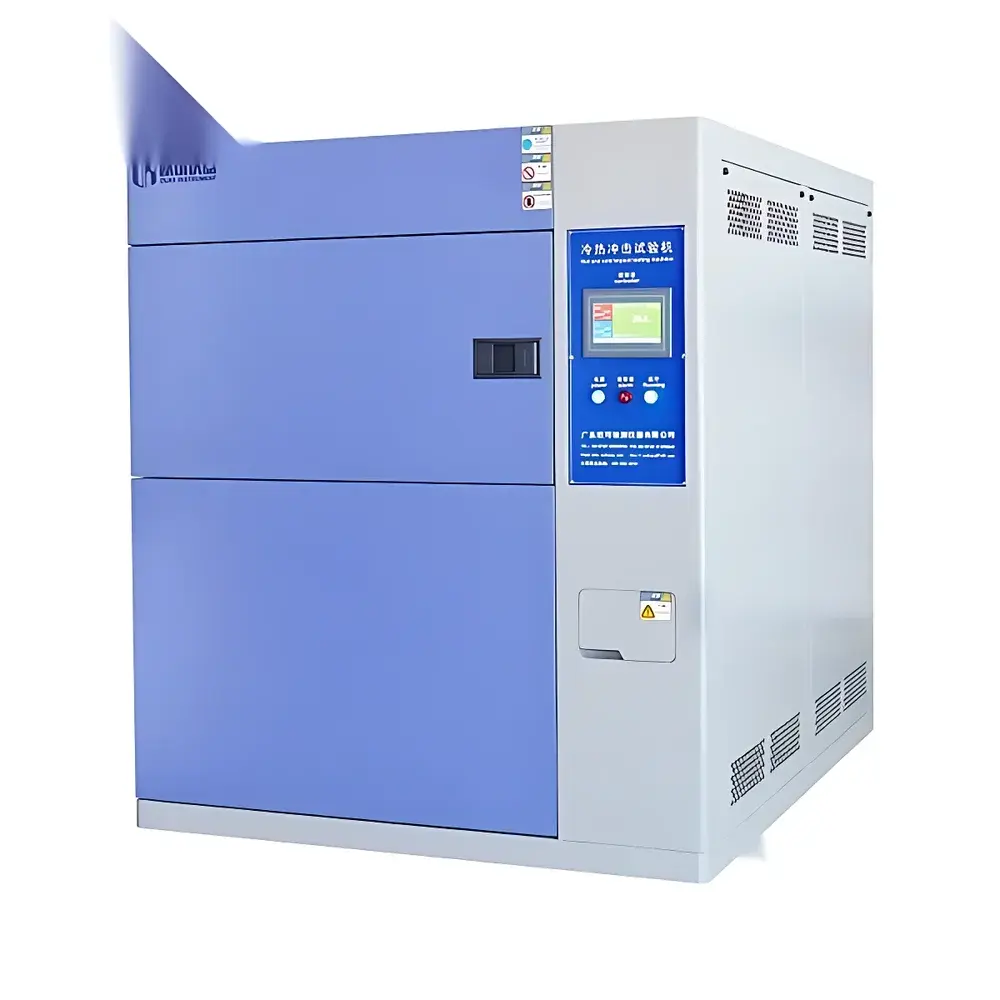
- Robust mechanical construction: SUS304B stainless steel interior with full TIG-welded, helium-leak-tested seams; external housing in powder-coated cold-rolled steel
- High-efficiency thermal isolation: ≥100 mm thick mineral wool insulation with vapor barrier layer, reducing heat loss by >40% versus conventional polyurethane foam
- Forced air circulation system comprising a high-torque centrifugal blower and multiple axial fans—ensuring uniform temperature distribution (±0.5°C at load, per IEC 60068-3-5)
- Comprehensive safety suite: compressor overheat/overcurrent/pressure fault detection, dry-heater protection, chamber over-temperature cutoff, low-water-level alarm, and electromechanical door interlock
- Standard 50 mm diameter cable port (left-side, sealed with silicone gasket), double-pane tempered observation window, adjustable stainless steel sample racks (2 sets), and internal fluorescent lighting
Sample Compatibility & Compliance
This chamber accommodates PCB assemblies, molded connectors, MEMS sensors, battery modules, optical housings, and medical device enclosures—up to 20 kg per load. Sample mounting fixtures are compatible with industry-standard DIN 41612, IPC-9701, and JEDEC JESD22-A104 test boards. The system meets and exceeds requirements for ISO 16750-4 (road vehicles), MIL-STD-810H Method 503.5 (thermal shock), IEC 60068-2-14 (change of temperature), and JIS Z 8702 (environmental testing). Optional configurations support GLP-compliant audit trails, 21 CFR Part 11–ready electronic signatures, and traceable calibration certificates (NIST-traceable RTDs).
Software & Data Management
Bundled PC software enables remote monitoring, script-based test sequencing (including hold-soak-transition-dwell logic), automatic report generation (PDF/CSV), and integration with enterprise MES/QMS platforms via RS485, Ethernet (Modbus TCP), or optional USB data export. All controllers log timestamped temperature/humidity values at user-defined intervals (1s–600s), with onboard memory retaining ≥30 days of continuous data. Audit trail functionality records operator login/logout events, parameter changes, and alarm activations—fully compliant with ISO/IEC 17025 and FDA-regulated environments.
Applications
- Qualification testing of semiconductor packages (QFN, BGA, CSP) per JEDEC J-STD-020 and AEC-Q200
- Validation of adhesive bond integrity in EV battery module housings under thermal cycling stress
- Failure mode analysis of optical lens mounts exposed to diurnal ambient extremes
- Accelerated life testing of conformal coatings on military-grade circuit boards
- Material compatibility screening for cryogenic-to-ambient sealants used in satellite payload bays
- Process capability assessment of reflow soldering profiles in SMT line qualification
FAQ
What is the minimum dwell time achievable between thermal zones?
Dwell times are programmable from 1 minute to 999 hours per zone, with typical minimum stable dwell set at 3 minutes to ensure thermal equilibrium per IEC 60068-2-14.
Can the chamber operate in humidity-coupled thermal shock mode?
Yes—optional surface-evaporation humidification (10–95% RH, ±3% RH accuracy) enables combined thermal-humidity shock per IEC 60068-2-30, though maximum RH is limited to 85% at +85°C.
Is calibration documentation provided with shipment?
Each unit ships with a factory calibration certificate covering chamber uniformity, transition rate verification, and sensor accuracy (±0.3°C), traceable to national metrology institutes.
What maintenance intervals are recommended for the refrigeration system?
Compressor oil and filter dryer replacement is advised every 24 months under continuous operation; annual inspection of refrigerant charge and blower motor bearings is required for GMP/GLP compliance.
How is thermal uniformity validated across the working volume?
Uniformity is verified using a 9-point thermocouple mapping procedure per IEC 60068-3-5, with results documented in the acceptance test report (ATR) prior to delivery.
Related Products


