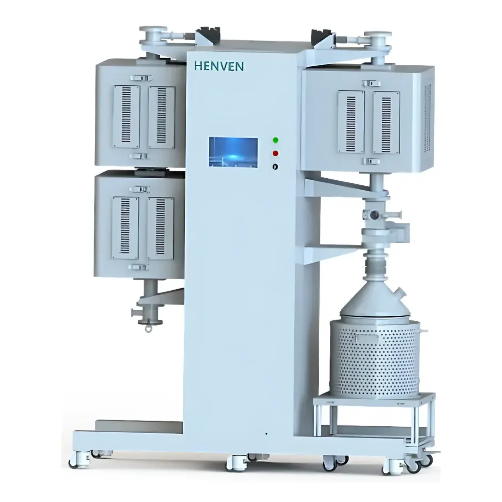
Henven Custom Thermal Shock Testing System
| Brand | Henven |
|---|---|
| Origin | Beijing, China |
| Manufacturer Type | Direct Manufacturer |
| Model | Custom-Engineered |
| Price Range | USD 140,000 – 280,000 |
| High-Temperature Range | 1400 °C |
| Low-Temperature Range | −20 °C |
| Thermal Shock ΔT Range | 1420 °C |
| Temperature Stability | ±0.5 °C |
| Heating Rate | 80 °C/min |
| Cooling Rate | 80 °C/min |
Overview
The Henven Custom Thermal Shock Testing System is an engineered solution for evaluating the thermal shock resistance of advanced ceramic and refractory materials—particularly silicon carbide (SiC) nuclear fuel pellets, structural components, and high-temperature functional ceramics. It operates on the principle of rapid, controlled thermal cycling between extreme temperature zones to induce thermal stress gradients that simulate real-world service conditions in nuclear reactors, aerospace thermal protection systems, and industrial furnace linings. The system implements a vertical dual-furnace architecture: an upper high-temperature furnace (up to 1420 °C) and a lower low-temperature zone comprising either a cryogenic furnace (−20 °C) or a precision thermostatic water bath (−20–100 °C). Sample transfer occurs vertically via a pneumatically actuated, inert-gas-shielded carousel mechanism with ≤1 s dwell time, minimizing thermal lag and ensuring reproducible ΔT exposure per cycle. This design conforms to the fundamental test logic defined in ASTM C1100 (Standard Test Method for Thermal Shock Resistance of Refractories) and supports method development aligned with ISO 10545-9 (Ceramic tiles — Part 9: Resistance to thermal shock).
Key Features
- Vertical dual-zone configuration: High-temperature furnace (top) and low-temperature chamber/water bath (bottom), enabling gravity-assisted, contamination-minimized sample transfer.
- SiC heating elements in both furnaces, rated for continuous operation from ambient to 1420 °C with ±0.5 °C temperature stability and ≤±0.5 °C uniformity over a 120 mm hot zone.
- Integrated thermostatic water bath: 20 L capacity, 304 stainless steel construction with ≥30 mm insulated wall thickness, temperature control precision ±0.1 °C across −20–100 °C range.
- Automated 5-position sample carousel: Designed for SiC cylindrical specimens (Ø5–35 mm × H5–35 mm); maintains ≥10 mm inter-sample spacing and ≥30 mm sample-to-furnace-wall clearance to ensure uniform thermal exposure.
- Dual environmental control: Vacuum capability (≤8 Pa, 4 L/s pumping speed) combined with triple-channel mass flow-controlled inert gas delivery (N₂, Ar, He; 0–100 mL/min per channel) for oxidation-sensitive testing under GLP-compliant atmospheres.
- Full programmable sequence control: Enables autonomous execution of multi-step protocols—including vacuum evacuation, gas purging, high/low zone temperature ramping, dwell times, thermal cycling count (up to 999 cycles), and inter-zone transfer—with hardware interlocks for overtemperature, overcurrent, and vacuum failure.
Sample Compatibility & Compliance
The system is validated for standardized SiC ceramic specimens per IAEA-TECDOC-1796 (Testing of Nuclear Fuel Cladding Materials) and supports custom geometries including rectangular blocks and cylinders within dimensional limits (5–35 mm in all axes). All thermal sensors use Class 1 thermocouples (Type S, tolerance ±0.25% t) positioned 8 mm from sample surface to meet ISO/IEC 17025 traceability requirements. Vacuum instrumentation employs Chengdu Zhenghua gauges (±20% relative error at low pressure), calibrated per manufacturer specifications. The mechanical transfer system incorporates non-contact position sensing and collision avoidance logic to eliminate handling-induced fracture—a critical requirement for brittle ceramic qualification per ASTM C1322 (Standard Practice for Fractography of Advanced Ceramics).
Software & Data Management
Control and data acquisition are managed through a Windows-based HMI platform featuring configurable recipe storage, real-time trend logging (temperature, vacuum, gas flow, position status), and export to CSV or XML formats. Audit trails record all parameter changes, operator logins, alarm events, and system state transitions—fully compliant with FDA 21 CFR Part 11 requirements for electronic records and signatures when deployed in regulated QA/QC environments. Optional OPC UA integration enables seamless connectivity to enterprise LIMS or MES platforms for automated report generation and long-term statistical process control (SPC) analysis of thermal shock failure thresholds.
Applications
- Evaluation of thermal shock resistance in nuclear-grade SiC fuel matrix materials and TRISO particle coatings.
- Qualification of ceramic matrix composites (CMCs) for turbine shroud and combustor liner applications.
- Development testing of refractory linings for metallurgical induction furnaces and glass melting tanks.
- Accelerated aging studies of thermal barrier coatings (TBCs) under cyclic thermal loading.
- Material screening for space-rated optical substrates and infrared window assemblies subjected to orbital thermal transients.
FAQ
What materials can be tested using this system?
The system is optimized for high-melting-point ceramics such as SiC, Al₂O₃, ZrO₂, and graphite-based composites. Metallic alloys with melting points below 1400 °C may be evaluated, though thermal expansion mismatch must be accounted for during fixture design.
Is vacuum capability mandatory for all test protocols?
No—vacuum operation is optional and typically used for oxidation-sensitive materials or baseline inert-atmosphere reference testing. The system supports ambient air, inert gas purge, or vacuum modes interchangeably within a single program.
Can the system accommodate non-SiC sample geometries?
Yes. The modular sample holder accepts custom fixtures for irregular shapes; however, maximum dimensions remain constrained by the 150 mm furnace bore and 120 mm uniform zone length.
How is temperature uniformity verified and maintained?
Uniformity is validated using a 5-point thermocouple mapping procedure per ASTM E220 prior to commissioning. Real-time monitoring via redundant sensors and closed-loop PID tuning ensures sustained compliance throughout operational life.
Does the system support remote monitoring and diagnostics?
Yes—via Ethernet-connected HMI with VNC-enabled remote desktop access, SNMP-based network alerts, and optional cloud telemetry for predictive maintenance scheduling.

")

