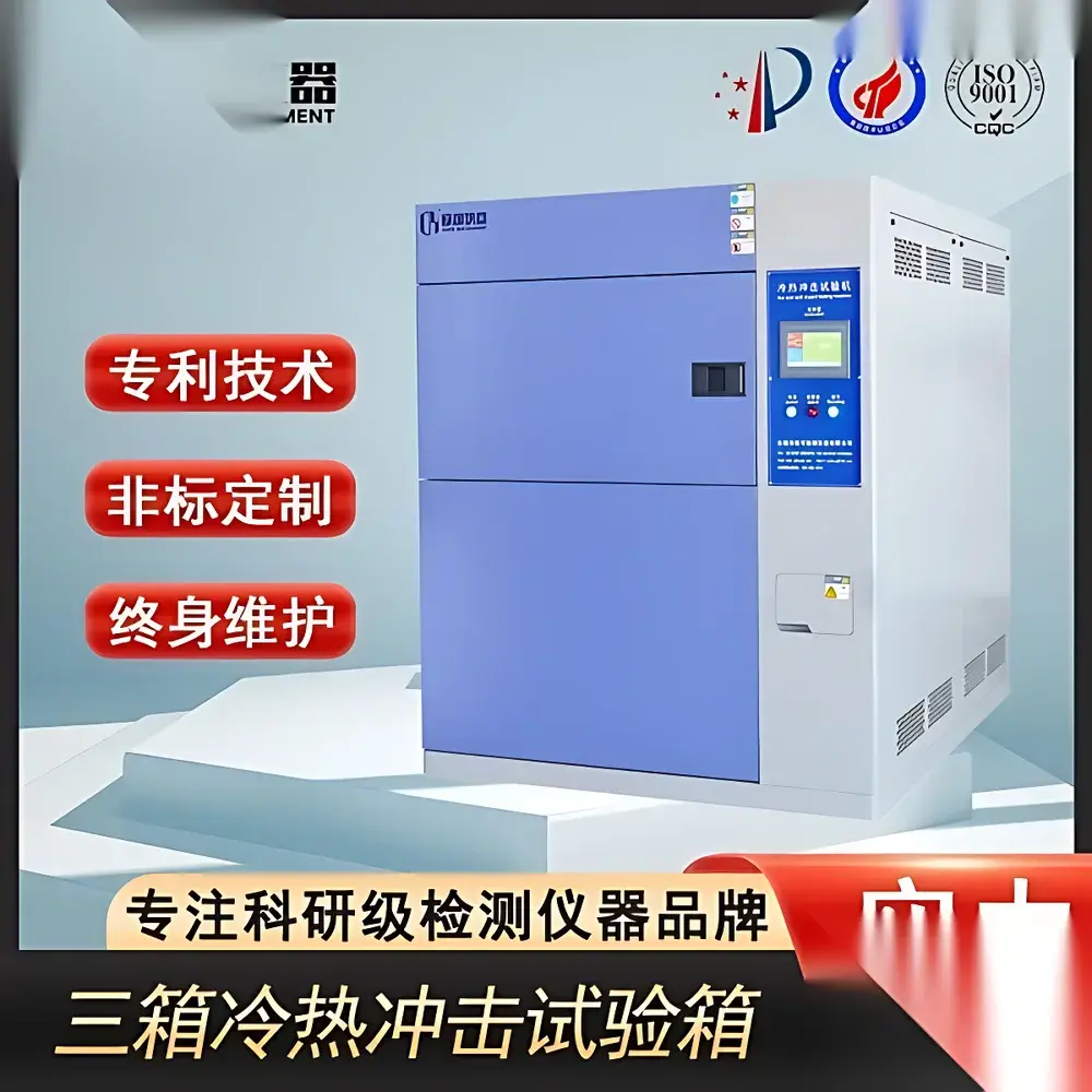
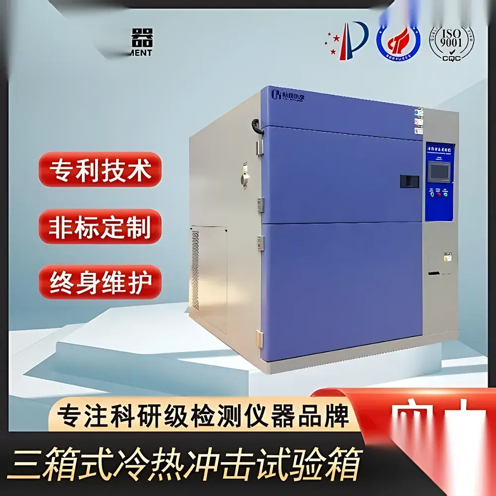
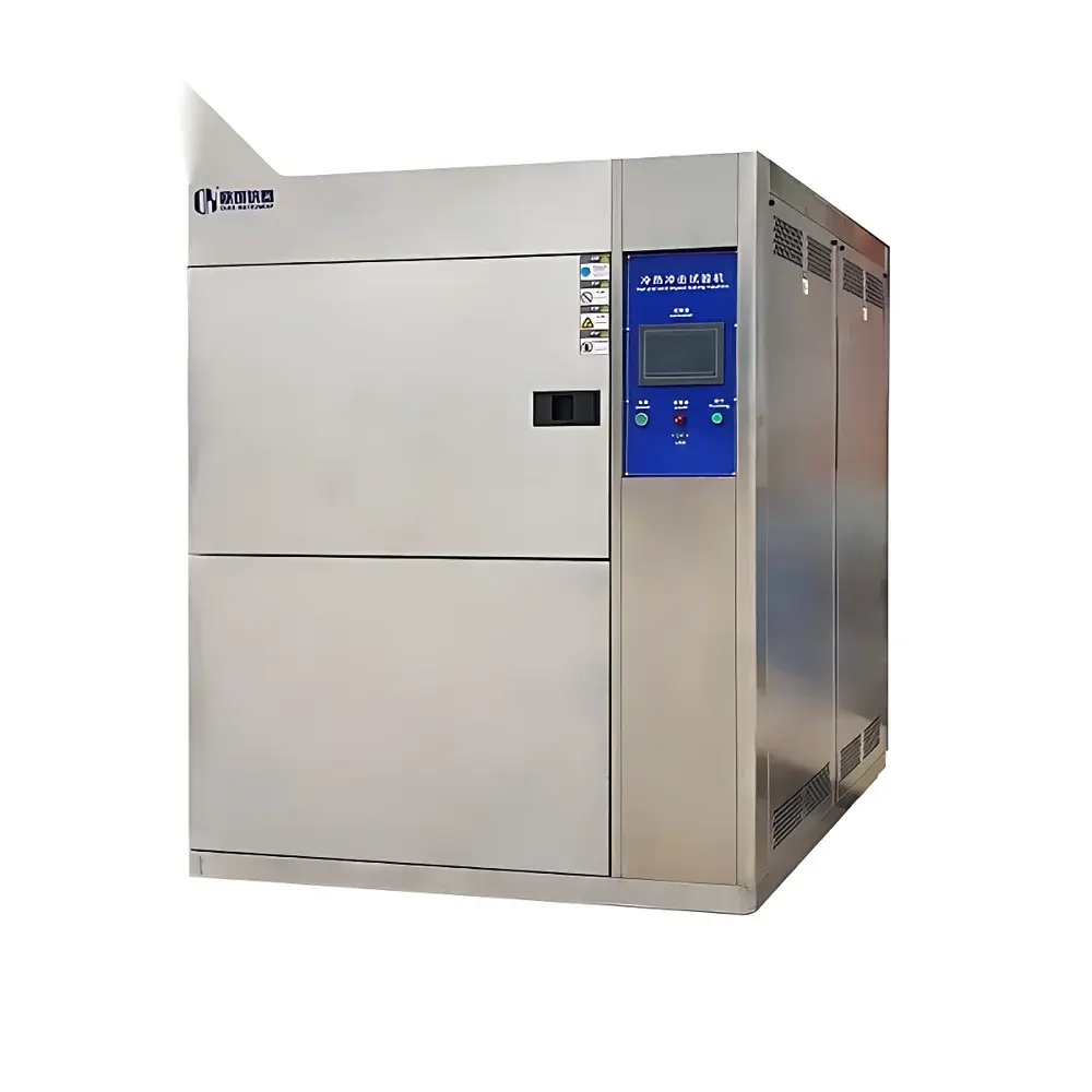
Thermal Shock Test Chamber – Three-Zone Static Sample Configuration
| Key Features | Three-zone design (high-temp chamber, low-temp chamber, test chamber) |
|---|---|
| Inner chamber wall thickness | 1.0–1.2 mm standard |
| Standard internal volumes | 50 L to 1000 L |
| Typical temperature ranges | −40 °C to +150 °C, −55 °C to +150 °C, or −70 °C to +150 °C |
Overview
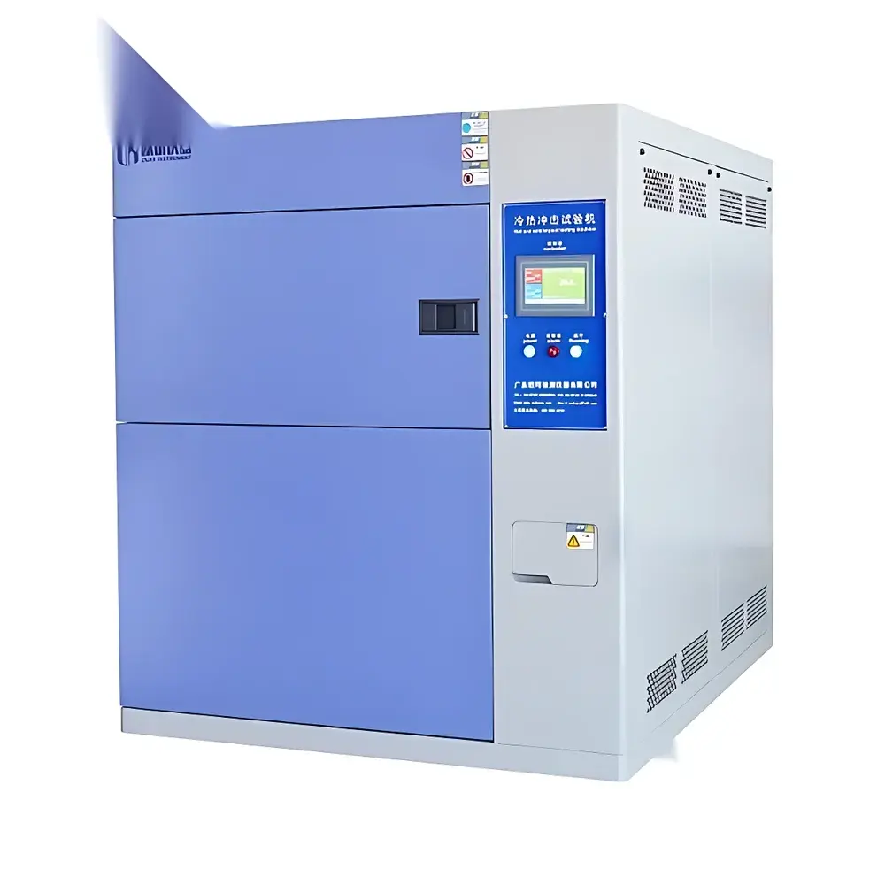
The Thermal Shock Test Chamber – Three-Zone Static Sample Configuration is an environmental stress screening instrument engineered for precise, repeatable thermal shock evaluation of electronic components, automotive modules, aerospace assemblies, and polymer-based products. Unlike two-chamber shuttle-type systems, this three-zone architecture isolates the test specimen in a dedicated, stationary chamber—eliminating mechanical handling, vibration transmission, and positional uncertainty during thermal transitions. High- and low-temperature chambers operate independently and remain thermally stabilized at setpoints, while the test chamber is alternately coupled via pneumatically actuated insulated doors. This static-sample methodology ensures signal integrity for concurrent electrical monitoring (e.g., real-time leakage current, impedance, or functional validation), making it suitable for reliability qualification under AEC-Q200, JEDEC J-STD-020, and IPC-9701 protocols.
Key Features
- Three-Zone Thermal Architecture: Physically segregated high-temperature (up to +150 °C), low-temperature (down to −70 °C), and ambient-capable test chambers minimize cross-contamination and improve thermal stability between cycles.
- No-Movement Sample Retention: The test specimen remains fixed throughout testing—critical for devices with fragile interconnects, MEMS structures, or embedded sensors where acceleration-induced stress must be excluded from failure analysis.
- Ambient Dwell Capability: Integrated room-temperature holding phase enables safe, tool-free loading/unloading without thermal exposure to operators or auxiliary equipment.
- Controlled Transition Profile: Temperature ramping between extremes follows a continuous, near-sinusoidal trajectory due to thermal mass dominance and proportional-integral-derivative (PID) tuning—reducing overshoot and improving repeatability across laboratories.
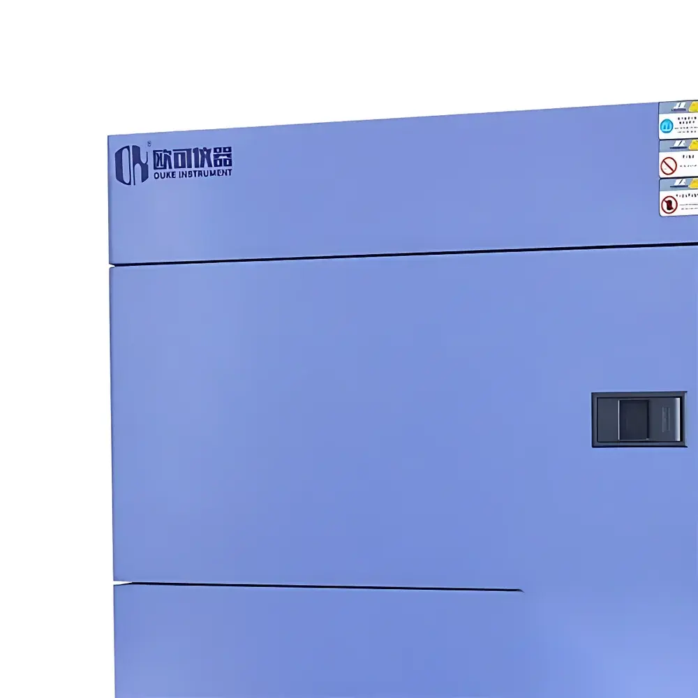
- Structural Integrity Design: Standard 1.0–1.2 mm cold-rolled stainless steel inner walls resist thermal bowing under sustained load and extreme gradients; optional electrophoretic-coated carbon steel variants available with RAL-matched finishes for facility-wide aesthetic alignment.
- Scalable Internal Volume Options: Configurable chamber capacities (50 L to 1000 L) accommodate both small PCBs and large automotive ECUs—dimensional planning should account for future product footprints and required air volume per IEC 60068-3-10 guidelines.
Sample Compatibility & Compliance
This chamber supports rigid and semi-rigid samples up to 350 × 450 × 550 mm (150 L configuration) with maximum payload capacities exceeding 50 kg—subject to uniform thermal mass distribution. It meets the physical test envelope requirements of multiple international standards including ISO 16750-4 (road vehicles), MIL-STD-810H Method 503.5 (temperature shock), JESD22-A104E (JEDEC solid-state devices), and IEC 60068-2-14 (basic environmental testing procedures). All units are supplied with traceable calibration certificates (NIST-traceable reference sensors) and support GLP/GMP-compliant operation when integrated with validated data acquisition systems.
Software & Data Management
Equipped with a touchscreen HMI running embedded Linux firmware, the system provides real-time graphical display of all chamber zone temperatures, door status, cycle count, and elapsed time. Optional Ethernet/RS-485 interfaces enable integration into centralized MES or LIMS platforms. Data logging occurs at user-selectable intervals (1–60 s) with CSV export capability and timestamped event markers (door open/close, setpoint change, alarm trigger). Audit trail functionality complies with FDA 21 CFR Part 11 requirements when paired with third-party electronic signature modules and role-based access control.
Applications
- Qualification of solder joint integrity in multilayer PCBAs subjected to rapid thermal cycling
- Evaluation of coefficient-of-thermal-expansion (CTE) mismatch in stacked-die packages
- Validation of encapsulant adhesion strength in optoelectronic housings
- Accelerated life testing of battery management systems under extreme ambient transients
- Screening of adhesive bond durability in composite structural assemblies
- Pre-qualification testing per automotive OEM-specific thermal shock specifications (e.g., GMW16276, Ford CETP 00.00-L-467)
FAQ
What distinguishes the three-zone static design from conventional two-chamber shuttle systems?
The absence of mechanical transfer eliminates inertial loading, positional drift, and thermal lag associated with moving baskets—yielding higher fidelity surface temperature tracking and enabling simultaneous electrical parametric measurement.
Can this chamber achieve true step-function temperature transitions?
No. Due to inherent thermal mass and convective heat transfer limitations, transitions follow a continuous, damped profile—consistent with real-world environmental exposure and aligned with IEC 60068-2-14 Annex B recommendations.
Is the stated temperature range applicable to the test chamber itself—or only to preconditioning zones?
All specified limits (e.g., −70 °C to +150 °C) refer to the operational bounds of the test chamber during active shock phases—not pre-conditioning zones—and are verified under load per ASTM E1512.
How does inner wall thickness affect long-term performance?
A minimum 1.0 mm wall thickness prevents warping at sustained extremes (>120 °C or 10,000 cycles.
What documentation is provided for regulatory audits?
Each unit ships with factory calibration reports, material compliance declarations (RoHS/REACH), CE marking documentation, and IQ/OQ protocol templates compatible with ISO 13485 and IATF 16949 quality management systems.


