ZEISS COMET5 2.0 High-Precision 3D Optical Scanning System
| Brand | ZEISS |
|---|---|
| Origin | Germany |
| Model | COMET5 2.0 |
| Camera Resolution | 1600 × 1200 pixels |
| Measurement Volumes (L×W×H) | 85×65×60 mm³ to 800×600×500 mm³ |
| 3D Point Spacing | 55–500 µm (configurable per field-of-view) |
| Acquisition Time | ≤ 0.6 s per scan |
| Interface | CAN bus + Gigabit Ethernet |
| Software Platform | COMETplus v8.x (64-bit, Windows 10/11) |
Overview
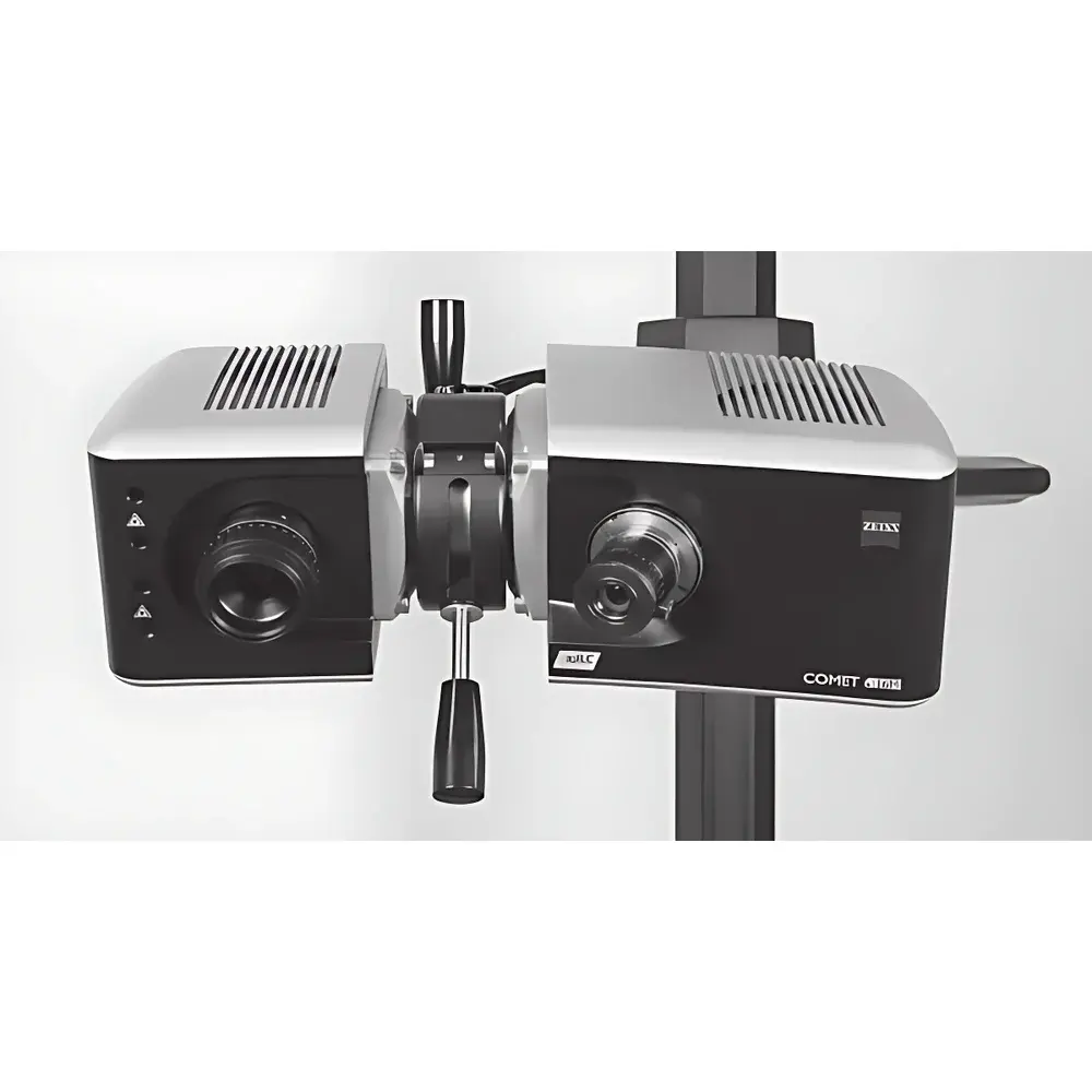
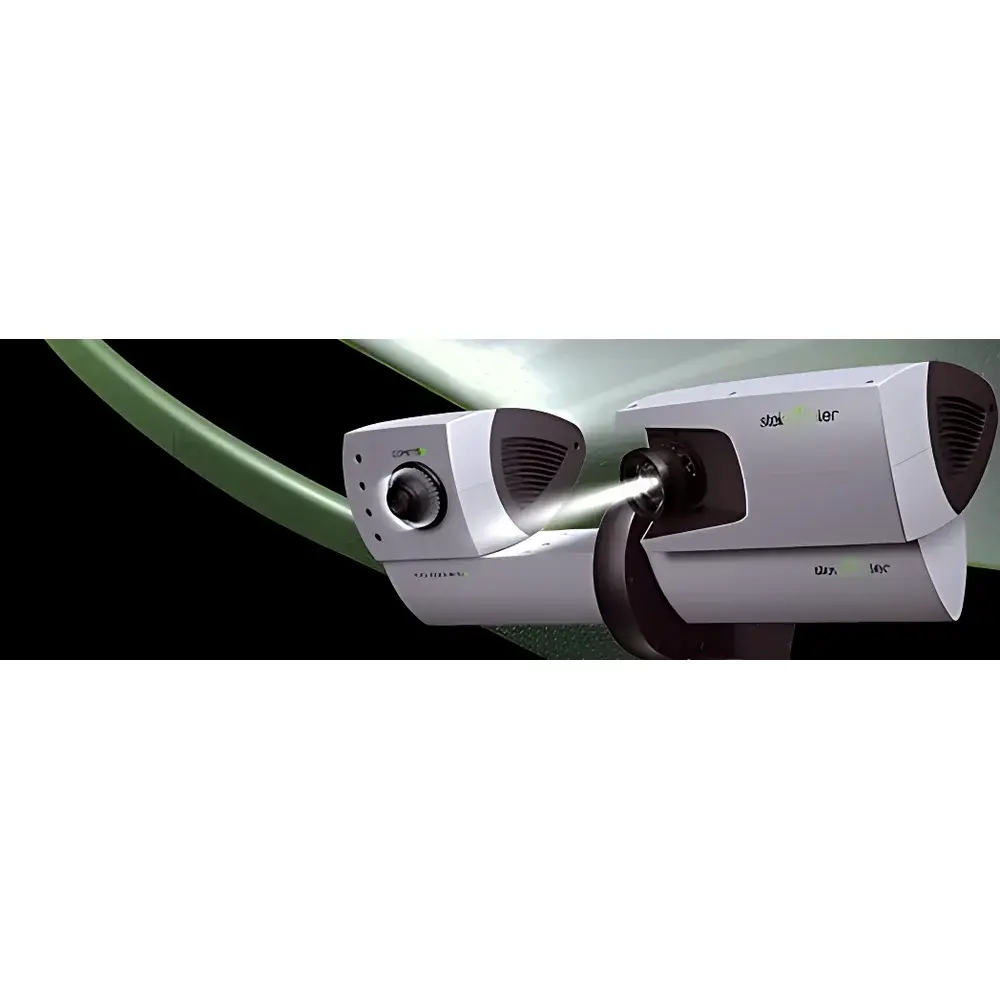
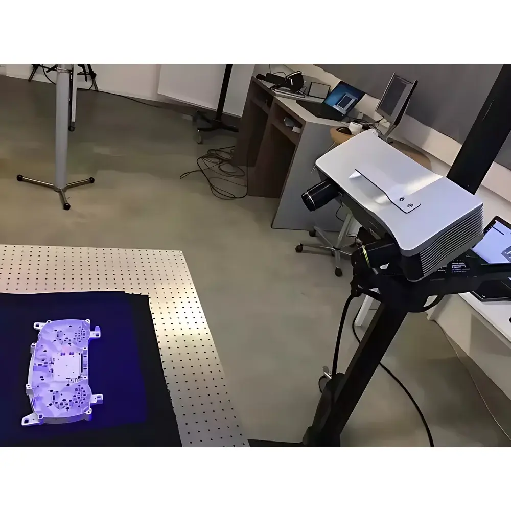
The ZEISS COMET5 2.0 is a high-precision, non-contact 3D optical scanning system engineered for metrology-grade dimensional inspection and reverse engineering in industrial R&D and production environments. Developed from the legacy of Steinbichler Optotechnik — the pioneer of structured-light photogrammetric measurement — the COMET5 platform implements localized triangulation using digitally projected fringe patterns. A calibrated white-light source projects sequential phase-shifted sinusoidal grids onto the object surface; a single high-resolution CCD camera captures these deformed patterns from a fixed baseline. Each pixel’s encoded phase shift is decoded to reconstruct surface topology with sub-pixel interpolation. This monocular principle eliminates parallax-induced misalignment between dual-camera systems, ensuring intrinsic geometric consistency across complex topographies — including deep cavities, overhangs, and bridged features — without shadow-induced data gaps or stitching artifacts. The system operates independently of ambient lighting and is thermally stabilized via fiber-coupled mercury-vapor illumination, minimizing thermal drift during extended operation.
Key Features
- Monocular structured-light architecture with patented single-lens imaging — guarantees intrinsic point-cloud coherence and eliminates inter-camera calibration drift.
- Digitally controlled LED or mercury-vapor light engine with fiber-optic delivery — isolates heat generation from the optical head, preserving long-term thermal stability and measurement repeatability.
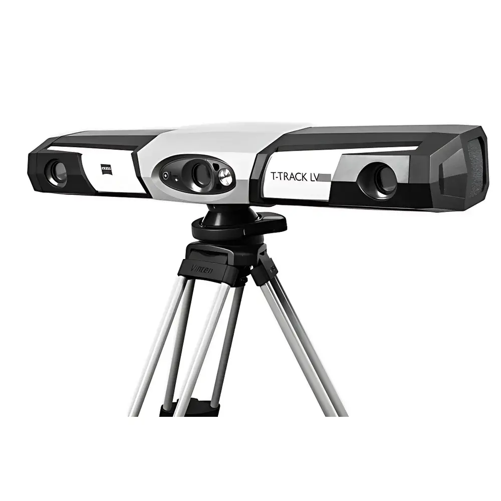
- Configurable field-of-view ranging from 50 mm to 800 mm diagonal — achieved via interchangeable lens sets and motorized focus, enabling rapid reconfiguration for micro- to macro-scale parts.
- Sub-0.6-second acquisition time per full-field scan — optimized for vibration-prone shop-floor deployment without motion blur or averaging artifacts.
- FEM-validated mechanical frame with granite base and carbon-fiber support structure — delivers rigidity > 250 N/µm and thermal expansion coefficient < 1.2 µm/m·K.
- Gigabit Ethernet + CAN bus dual-interface architecture — ensures deterministic data throughput (> 950 Mbps sustained) and real-time diagnostics under industrial EMI conditions.
- VDI/VDE 2634 Part 2 Class 1 certification — validated traceable uncertainty down to 1.8 µm + L/150,000 (L = measured length in mm) across all FOV configurations.
Sample Compatibility & Compliance
The COMET5 2.0 accommodates matte, semi-gloss, and lightly textured surfaces without mandatory surface preparation. Specular or transparent objects require standardized matting spray (e.g., ZEISS Anti-Reflective Coating A12), compliant with ISO 10723:2018 for temporary metrology coatings. The system supports automated part positioning via optional rotary stages (ISO 10952-compliant) or robotic integration (ROS 2 Foxy / EtherCAT slave interface). All hardware and firmware comply with CE, UL 61010-1, and EMC Directive 2014/30/EU. Data integrity protocols align with FDA 21 CFR Part 11 requirements when used with COMETplus Audit Trail Module (optional), providing electronic signatures, immutable logs, and role-based access control for GLP/GMP-regulated workflows.
Software & Data Management
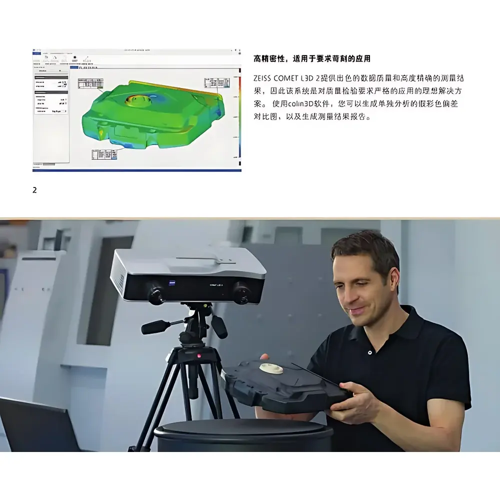
COMETplus v8.x serves as the native processing environment — a 64-bit Windows application supporting multi-threaded point-cloud registration, noise filtering, and NURBS surface fitting. Core algorithms include iterative closest point (ICP) with feature-constrained alignment, intelligent outlier suppression based on local curvature variance, and adaptive mesh simplification preserving geometric fidelity (STL export with user-defined chordal deviation ≤ 1 µm). The software natively imports GD&T annotations from STEP AP242 and exports ASME Y14.5-compliant inspection reports (PDF/XML). Remote operation is supported via tablet PC over WLAN using COMET Remote Control SDK, enabling live scan monitoring and parameter adjustment without physical workstation access. All raw image sequences and processed datasets are stored in vendor-agnostic HDF5 format with embedded metadata (exposure time, lens ID, calibration timestamp).
Applications
- First-article inspection of turbine blades, impellers, and injection-molded plastic housings — verifying form error against CAD within ±2.5 µm at 200 mm FOV.
- Tool wear monitoring in die-casting dies — tracking erosion progression on cavity surfaces over 500+ cycles with < 0.8 µm/month resolution.
- Reverse engineering of legacy aerospace components lacking CAD documentation — generating watertight, topology-optimized meshes suitable for generative design input.
- In-line quality gate verification prior to CNC machining — integrated with MES via OPC UA server module to flag deviations exceeding ISO 2768-mK tolerances.
- Biomechanical research: digitizing anatomical phantoms for finite element model validation under ASTM F2943-21 protocols.
FAQ
What calibration standards does the COMET5 2.0 support?
It accepts ZEISS-certified ceramic reference spheres (Ø10–50 mm, sphericity ≤ 0.1 µm) and VDI/VDE 2634-compliant step gauges for periodic verification. Calibration certificates are issued per ISO/IEC 17025:2017 by ZEISS Metrology Services.
Can the system operate in ambient factory lighting?
Yes — the narrowband optical filter (center wavelength 546 nm ± 5 nm) and synchronized projection shutter reject > 99.2% of ambient broadband irradiance, enabling stable operation under 50,000 lux fluorescent lighting.
Is robot integration supported out-of-the-box?
Standard EtherCAT and RS-422 interfaces enable direct coupling with ABB, KUKA, and Universal Robots controllers. ZEISS provides ROS 2 drivers and trajectory optimization libraries for path planning with minimal point-cloud distortion.
How is measurement uncertainty quantified and documented?
Each scan includes embedded uncertainty maps derived from sensor noise modeling, lens distortion correction residuals, and triangulation geometry Jacobians. Full uncertainty budgets conform to GUM (JCGM 100:2008) and are exportable as CSV or PDF.
Does COMETplus support automated GD&T reporting per ASME Y14.5–2018?
Yes — position, profile, flatness, and concentricity evaluations are performed against nominal CAD with statistical process control (SPC) charting and Cp/Cpk calculation. Reports include annotated cross-sections and deviation heatmaps.