Kanomax 6162 High-Temperature Thermal Anemometer for Boiler and Engine Exhaust Monitoring
| Brand | Kanomax |
|---|---|
| Model | 6162 |
| Type | Thermal Anemometer |
| Resolution | 0.01 m/s |
| Velocity Range | 0–50.0 m/s (with temperature-dependent zero-velocity thresholds) |
| Accuracy | ±3% of reading or ±(1% of reading + 1 °C) for temperature |
| Operating Temperature Range | 0–500 °C (probe-dependent) |
| Humidity Range | 0–100% RH |
| Output | 0–1 V analog |
| Data Storage | 999 records |
| Interface | RS-232C |
| Probe Cable | PTFE-insulated, rated to 200 °C |
| Power | 6 × 1.5 V AA batteries or 12.5 V DC adapter (450 mA) |
Overview
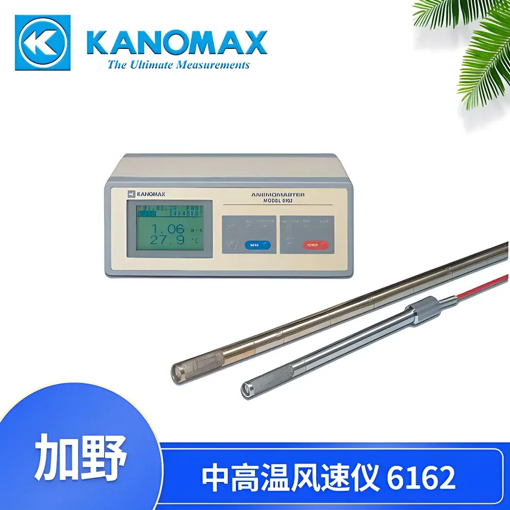
The Kanomax 6162 is a purpose-engineered high-temperature thermal anemometer designed for reliable, real-time velocity and temperature measurement in aggressive exhaust environments—including industrial boiler stacks, internal combustion engine exhaust ducts, waste heat recovery systems, and thermal process flues. It operates on constant-temperature anemometry (CTA) principles: a heated sensing element (typically a platinum-coated thermistor or thin-film resistor) is maintained at a fixed temperature differential above ambient; convective cooling by gas flow alters the power required to sustain that delta-T, which is linearly correlated to mass flow velocity under calibrated conditions. Unlike pitot tubes or ultrasonic sensors, the 6162 delivers direct volumetric velocity readings without requiring pressure/temperature compensation—critical for transient, high-temperature exhaust streams where static pressure gradients and gas composition vary significantly. Its probe architecture supports continuous operation up to 500 °C, with three interchangeable probe variants (0203, 0204, 0205) enabling optimization for duct geometry, particulate loading, and thermal inertia requirements.
Key Features
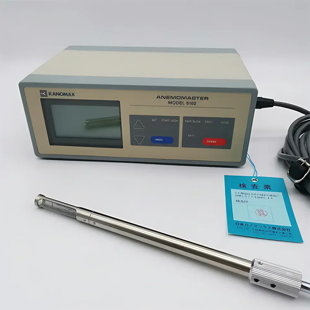
- Triple-probe compatibility: Selectable stainless-steel probes (Φ11×208 mm, Φ14×500 mm, Φ14×1000 mm) with PTFE-insulated cables rated to 200 °C—enabling adaptation to narrow stacks, deep insertion points, or high-turbulence zones.
- Temperature-compensated velocity measurement: Zero-velocity threshold automatically adjusts per temperature band (e.g., V₀ = 0.2 m/s at 0–99 °C; V₀ = 1.0 m/s at 300–400 °C), minimizing low-flow drift in elevated thermal environments.
- Integrated dual-parameter acquisition: Simultaneous capture of velocity (0.01 m/s resolution) and temperature (±1% rdg + 1 °C accuracy) eliminates time-synchronization errors between separate instruments.
- On-device data management: Stores 999 timestamped measurement sets with statistical functions (min/max/avg) — essential for compliance-driven stack testing protocols requiring traceable field averages.
- Analog output (0–1 V) and RS-232C interface support integration into SCADA systems, PLC-based emission monitoring platforms, or custom DAQ setups compliant with IEC 61000-4 EMC standards.
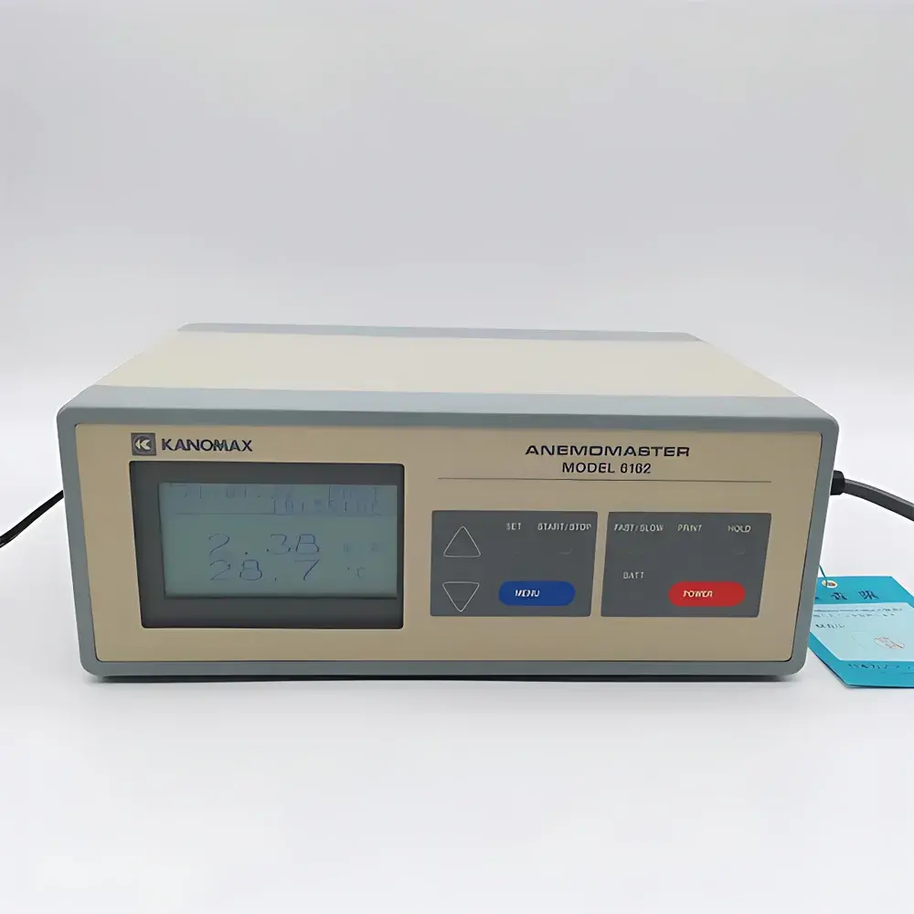
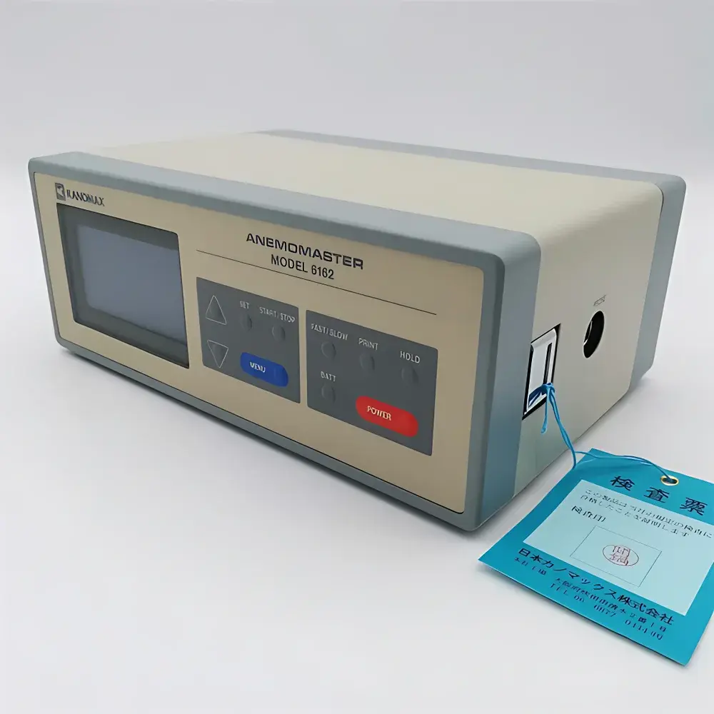
- Robust field architecture: Main unit (220 × 150 × 85 mm, 1.8 kg) features IP54-rated enclosure, battery-backed operation (6 × AA), and optional AC adapter (12.5 V / 450 mA) for extended stationary deployments.
Sample Compatibility & Compliance
The 6162 is validated for use in dry or moderately humid exhaust gases (0–100% RH), including flue gas from coal-, oil-, and natural gas-fired boilers; diesel and gasoline engine exhaust; and catalytic converter outlet streams. It is not intended for corrosive or condensing environments (e.g., wet scrubber outlets or unconditioned biomass flue gas with tar carryover). While not certified to EN 15267 or EPA Method 2F per se, its measurement methodology aligns with ISO 16811:2014 (thermal anemometers for fluid velocity) and supports data collection workflows compatible with ISO 5167-4 (exhaust flow rate determination via velocity integration) and ASTM D6784-22 (stack testing for mercury and other pollutants). The device’s audit-ready data logging satisfies GLP-aligned field documentation requirements for QA/QC reporting.
Software & Data Management
Data export is performed via RS-232C using Kanomax-supplied PC software (Windows-compatible), which enables CSV export, profile plotting (velocity vs. temperature vs. time), and cross-sectional averaging when paired with user-defined duct area inputs. The software maintains full metadata (probe ID, calibration date, operator ID, location tag), supporting 21 CFR Part 11–compliant audit trails when deployed with electronic signature modules. No cloud dependency: all processing occurs locally, ensuring data sovereignty and compliance with EU GDPR and industrial cybersecurity policies (IEC 62443 Level 1).
Applications
- Regulatory stack testing per local environmental agency protocols (e.g., China’s HJ/T 397, US EPA Performance Specification 11).
- Boiler efficiency audits—calculating actual volumetric flow for combustion air/fuel ratio analysis and heat loss estimation.
- Engine dynamometer exhaust characterization during transient cycle testing (e.g., WHSC, NTE).
- Commissioning and balancing of industrial exhaust hoods, fume incinerators, and thermal oxidizers.
- Validation of CFD model boundary conditions in high-temperature ventilation systems.
FAQ
Can the 6162 be used in wet or corrosive exhaust streams?
No. Condensation, acid dew point exposure, or high particulate loading (>5 g/Nm³) may damage the sensor element or insulating sheath. Use only in dried, filtered, or pre-conditioned streams.
Is probe calibration traceable to national standards?
Yes. Each probe is supplied with a factory calibration certificate traceable to JCSS (Japan Calibration Service System) standards, with optional NIST-traceable recalibration available through Kanomax authorized service centers.
How is cross-sectional flow calculated?
Enter duct cross-sectional area (m²) into the instrument; it computes volumetric flow (Nm³/h or ft³/min) using average velocity and measured temperature—applying ideal gas law corrections internally.
Does the device support automatic averaging across multiple traverse points?
No. Traverse averaging must be performed externally using exported data; however, the 999-record buffer allows sequential point measurements within a single session.
What is the recommended recalibration interval?
Annually under normal use; every 6 months in continuous high-temperature service (>400 °C) or after mechanical shock or contamination events.