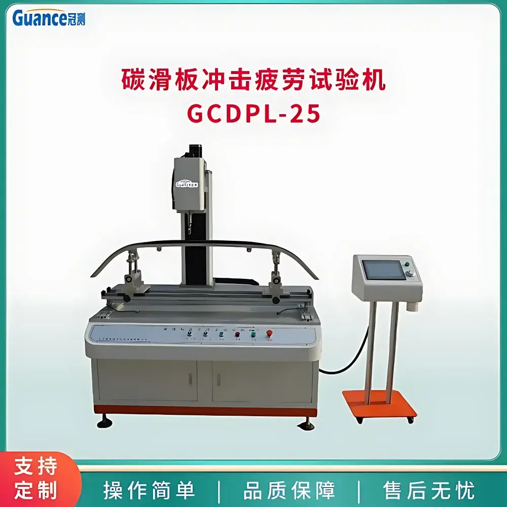
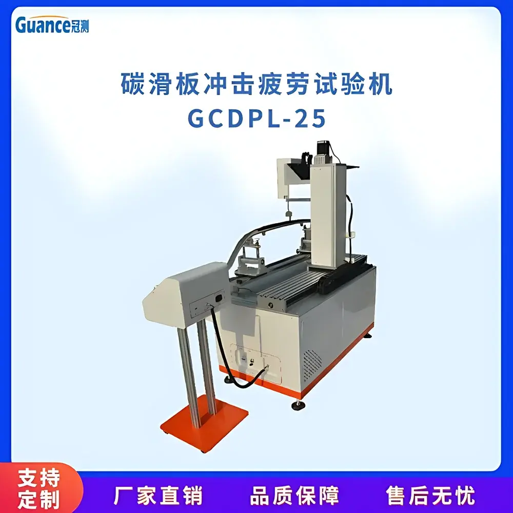
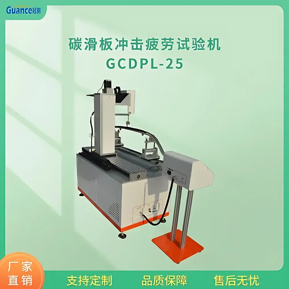
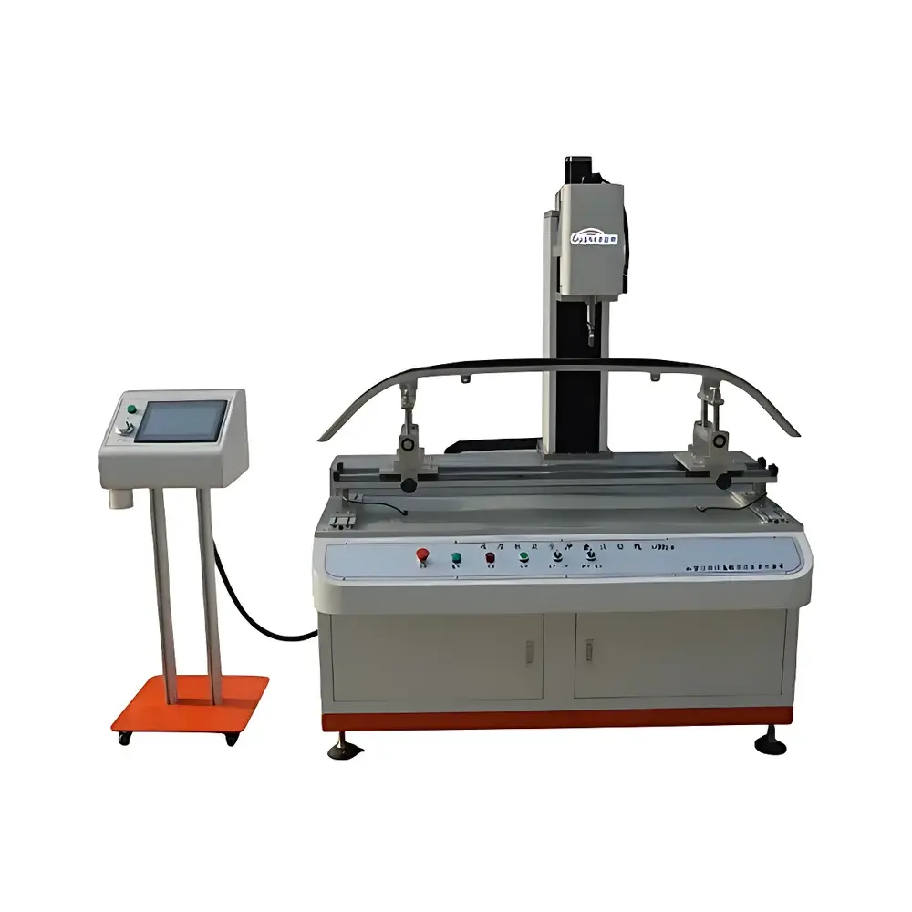
GuanCe Instruments GCDPL-25 Carbon Pantograph Strip Impact Fatigue Testing Machine
| Brand | GuanCe Instruments |
|---|---|
| Origin | Hebei, China |
| Manufacturer Type | Authorized Distributor |
| Country of Origin | China |
| Model | GCDPL-25 |
| Max Test Force | 10 kN |
| Frequency Range | a) 10 mm stroke @ 7 Hz (150 N impact force), b) 4 mm stroke @ 10 Hz (150 N impact force) |
| Host Weight | 500 kg |
| Input Voltage | AC 220 V, 50 Hz |
| Rated Power | 2 kW |
| Horizontal Travel | 1100 mm |
| Vertical Travel | 300 mm |
| Rotary Servo Motor Power | 1.5 kW |
| Load Cell Capacity | 1 kN |
| Overall Dimensions (L×W×H) | 1500 × 1000 × 1940 mm |
Overview
The GuanCe Instruments GCDPL-25 Carbon Pantograph Strip Impact Fatigue Testing Machine is an electromechanically controlled fatigue test system engineered for evaluating the dynamic mechanical durability of carbon-based current-collecting strips used in railway pantograph applications. It operates on a servo-driven impact principle—employing a high-torque rotary servo motor coupled with an eccentric cam mechanism to generate repeatable, time-controlled impact loads at defined stroke amplitudes and frequencies. Unlike quasi-static or cyclic tensile fatigue systems, the GCDPL-25 replicates real-world operational stress conditions experienced by overhead line contact components, where repeated localized mechanical shock induces microcracking, delamination, and progressive material degradation. The system delivers calibrated impact energy through a rigidly guided striker head, with dual 1 kN load cells mounted beneath the specimen platform enabling real-time force summation and validation of applied impulse magnitude. Designed for laboratory-based quality assurance and R&D validation, it supports standardized evaluation protocols aligned with IEC 62196, EN 50317, and TB/T 2809–2017 (Chinese Railway Industry Standard for Carbon Sliding Strips).
Key Features
- Precisely programmable impact parameters: selectable stroke (4 mm or 10 mm) with corresponding frequency limits (10 Hz or 7 Hz) while maintaining constant nominal impact force (150 N), ensuring reproducible energy input per cycle.
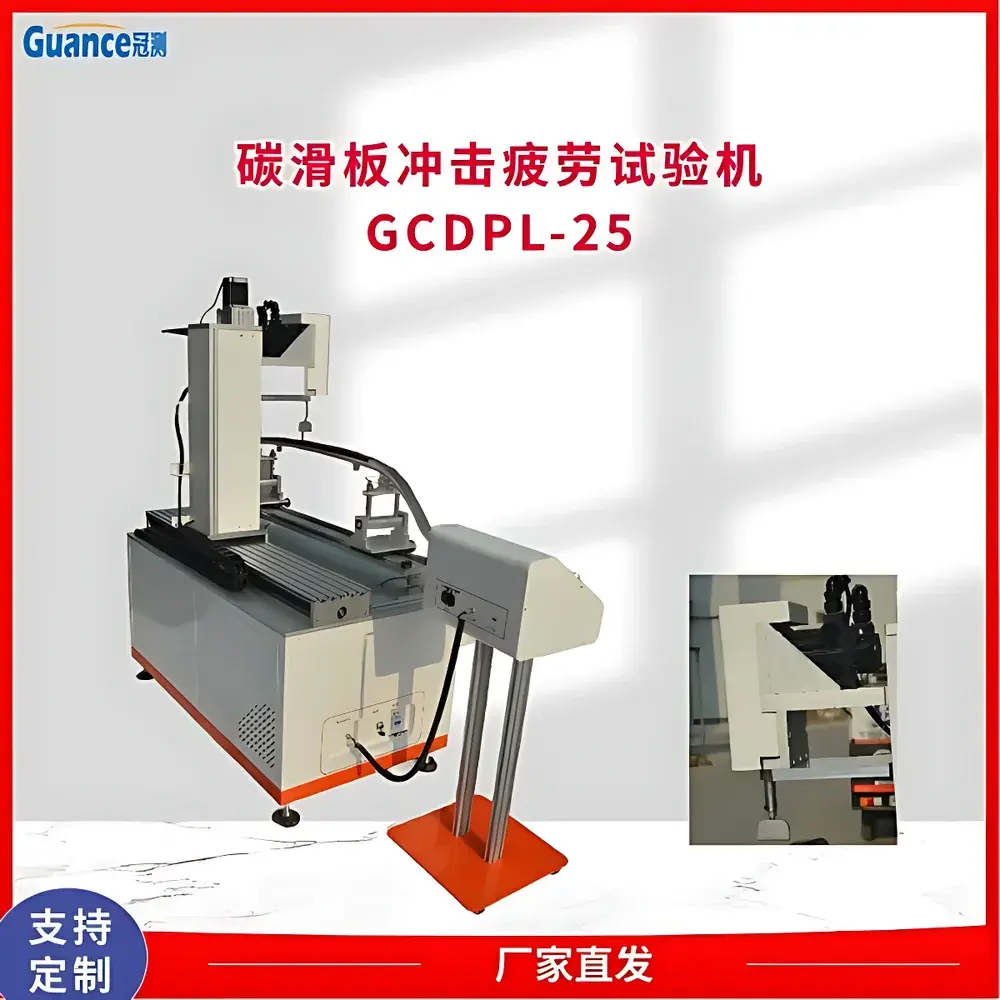
- Three-axis coordinated motion architecture: independent horizontal (1100 mm travel), vertical (300 mm travel), and impact-axis (eccentric-driven) actuation—each driven by stepper or servo motors with linear guidance via ball screws and precision linear rails/bearings.
- Integrated force monitoring: dual 1 kN strain-gauge load cells installed in parallel under the test platform provide redundant, synchronized measurement of total impact reaction force; data logged via Siemens PLC with ±0.5% full-scale accuracy.
- Human-machine interface: 10-inch industrial touchscreen HMI enables intuitive setup of test sequences—including total impact count, elapsed time threshold, and automatic termination logic—with real-time display of force waveform, cycle counter, and positional feedback.
- Robust mechanical construction: fabricated steel frame with vibration-damping feet and reinforced mounting interfaces; total mass of 500 kg ensures stable operation during high-frequency impact cycles without resonant amplification.
- Compliance-ready control architecture: PLC-based logic supports audit trail generation (via optional external logging), parameter lockout functions, and user-level access control—facilitating alignment with GLP and internal QA documentation requirements.
Sample Compatibility & Compliance
The GCDPL-25 accommodates standard carbon pantograph strip specimens up to 1200 mm in length and 100 mm in width, secured using modular clamping fixtures adaptable to varying cross-sectional geometries (e.g., C-type, T-type, or dovetail profiles). Specimen mounting platforms include adjustable lateral stops and torque-limited fastening handles to ensure consistent boundary conditions across test series. While not certified to ISO 12107 or ASTM E466 per se (as those standards govern uniaxial axial fatigue), the machine’s operational envelope and measurement traceability support method development for custom fatigue protocols referenced in EN 50317 Annex B (mechanical endurance testing of collector strips) and GB/T 25320–2010 (Chinese national standard for electric locomotive component testing). All electrical subsystems comply with IEC 61000-6-2 (immunity) and IEC 61000-6-4 (emission) requirements for industrial environments.
Software & Data Management
Data acquisition and sequence execution are managed entirely by a Siemens S7-1200 PLC, which samples load cell outputs and encoder position signals at ≥1 kHz. Raw time-series force data, cycle counts, and trigger timestamps are buffered onboard and exported via USB or Ethernet to CSV-formatted files compatible with MATLAB, Python (NumPy/Pandas), or commercial statistical analysis platforms. The HMI firmware includes built-in data filtering (moving average, low-pass), event tagging (start/stop, overload detection), and configurable alarm thresholds (e.g., force deviation >±5% from setpoint triggers immediate halt). For regulated environments, optional OPC UA server integration enables connection to LIMS or MES systems supporting 21 CFR Part 11-compliant electronic signatures and audit trails when deployed with validated third-party software layers.
Applications
- Comparative assessment of carbon composite formulations (e.g., resin-bonded graphite vs. metal-impregnated carbon) under simulated pantograph arcing and mechanical shock loading.
- Validation of manufacturing process consistency—e.g., sintering temperature effects on fracture resistance or binder distribution homogeneity.
- Pre-certification screening for new strip designs prior to full-scale vehicle integration testing on rolling stock.
- Root-cause analysis of field failures by correlating lab-induced damage morphology (microcrack density, edge chipping, layer separation) with service history data.
- Supporting technical bid documentation for rail infrastructure tenders requiring demonstrable fatigue life verification per customer-specified duty cycles.
FAQ
What is the maximum allowable specimen thickness for mounting on the GCDPL-25?
The vertical travel clearance above the platform permits specimens up to 65 mm in height; fixture adaptors may be supplied for non-standard geometries upon request.
Can the impact force be varied beyond the nominal 150 N setting?
No—the mechanical design fixes impact energy via cam geometry and motor speed; force variation requires hardware modification and recalibration, which voids factory calibration validity.
Is remote monitoring or network connectivity supported out-of-the-box?
Standard configuration includes Ethernet port for file export and basic PLC diagnostics; full SCADA integration requires optional firmware upgrade and configuration support.
Does the system meet CE marking requirements for export to the EU?
The base unit complies with EMC Directive 2014/30/EU and Low Voltage Directive 2014/35/EU; CE declaration is provided with delivery, though end-user responsibility remains for application-specific risk assessment per Machinery Directive 2006/42/EC.
How frequently should load cell calibration be performed?
Annual recalibration against traceable dead-weight standards is recommended; interim verification using known reference masses can be conducted quarterly per internal QA procedures.


