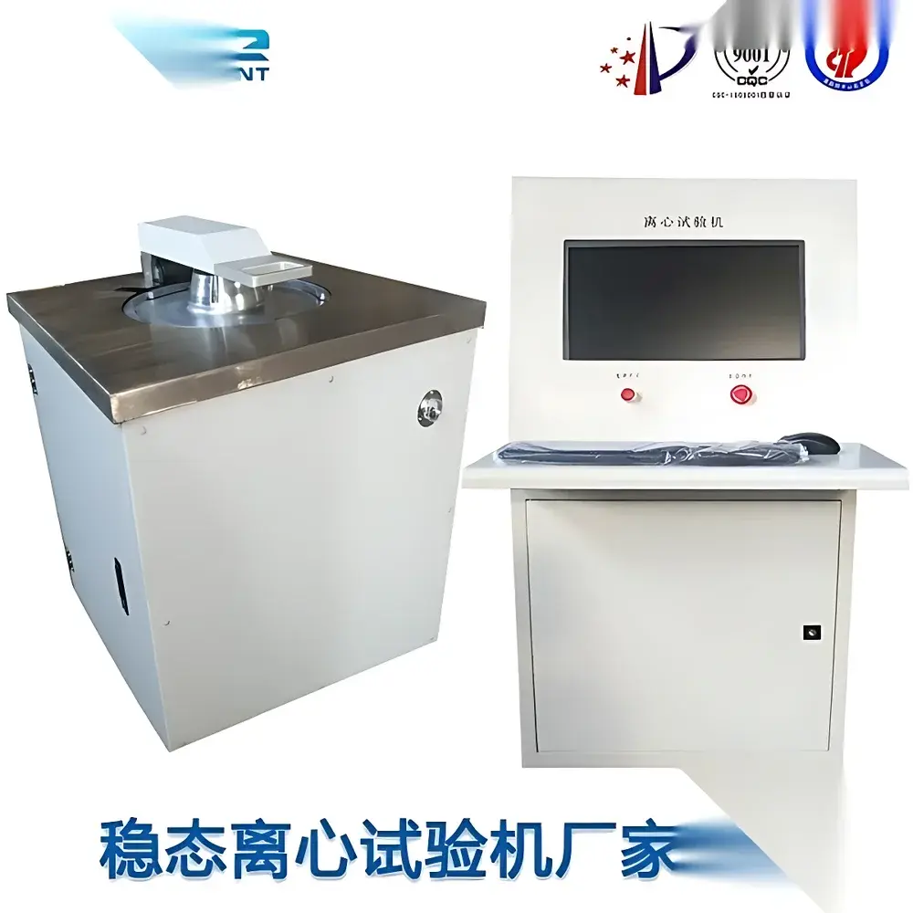
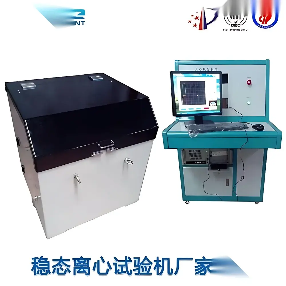
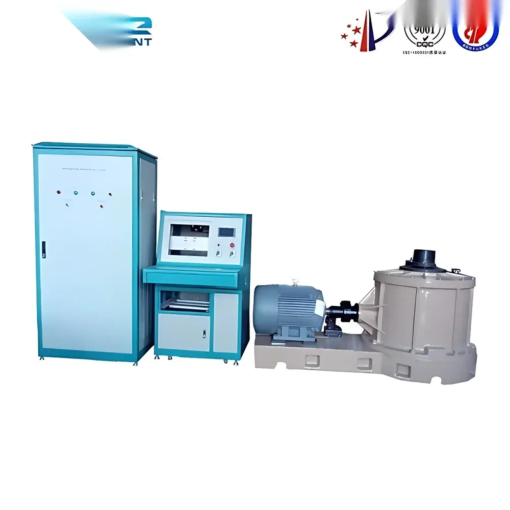
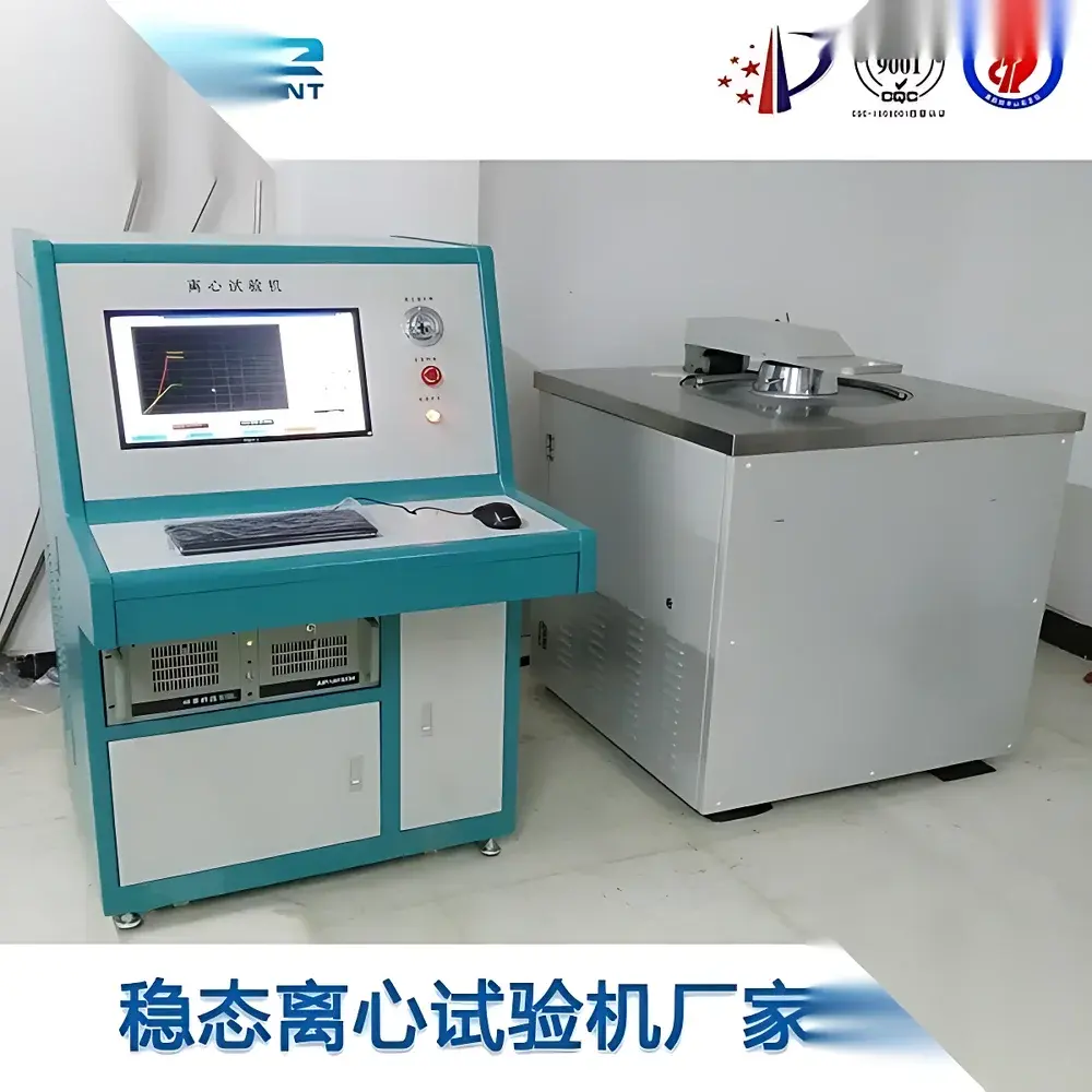
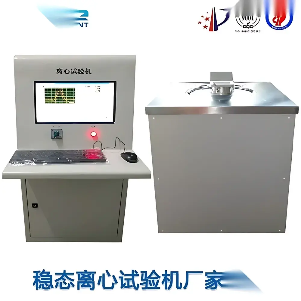
Steady-State Acceleration Simulation Test System
| Brand | Other Brands |
|---|---|
| Origin | Imported |
| Manufacturer Type | Authorized Distributor |
| Price | USD 28,000 (FOB) |
| Acceleration Range | 30–200,000 m/s² |
| Test Directions | X, Y, Z orthogonal axes |
| Max Specimen Height | 200–300 mm |
| Specimen Mounting Radius | 200–1000 mm |
| Startup Time | ≤3–5 min |
| Continuous Operation Duration | 30–60 min |
| Power Supply | AC 380 V, 1.5–6.5 kVA |
| Dimensions (L×W×H) | 924×910×1242 mm to 1953×470×993 mm |
| Weight | 1000–2300 kg |
| Compliance | MIL-STD-810F, MIL-STD-883C, MIL-STD-202F, GJB 150, GJB 360, GB/T 2423, IEC 60068-2-27 |
Overview
The Steady-State Acceleration Simulation Test System is an electromechanical high-g test platform engineered for precise, repeatable application of sustained unidirectional acceleration loads—excluding gravitational acceleration—to electronic components, microelectromechanical systems (MEMS), printed circuit board assemblies (PCBAs), and small-scale avionics hardware. Unlike transient shock or vibration testing, this system generates controlled, steady-state inertial acceleration fields via high-torque rotary actuation coupled with centrifugal force amplification. The core principle relies on centripetal acceleration (a = ω²r), where angular velocity (ω) and specimen radial offset (r) are precisely regulated to achieve target g-levels across a broad dynamic range (30–200,000 m/s², i.e., ~3–20,400 g). Designed for laboratory-grade qualification and reliability screening, the system enables structural integrity verification under prolonged over-acceleration stress, supporting failure mode analysis related to solder joint fatigue, wire bond detachment, die cracking, and mechanical resonance-induced deformation.
Key Features
- Modular rotor configuration supporting 4–64 independent test stations—enabling parallel evaluation of multiple specimens under identical acceleration profiles.
- Three-axis sequential test capability: Specimens undergo rigorously controlled acceleration exposure in X, Y, and Z orientations without manual repositioning, ensuring full-axis mechanical stress mapping.
- Industrial-grade programmable logic controller (PLC) integrated with real-time motion control firmware, delivering <±0.5% acceleration accuracy and <1% repeatability over extended duty cycles.
- High-rigidity aluminum-alloy rotor assembly with dynamically balanced spindle shaft and low-backlash harmonic drive transmission—minimizing torsional oscillation and thermal drift during sustained operation.
- Dedicated specimen mounting interface accommodating heights up to 300 mm and radial installation offsets from 200 mm to 1000 mm—facilitating flexible fixture design per MIL-STD-883C Test Method 2001 requirements.
- Integrated safety interlock architecture compliant with ISO 13857 and IEC 61508 SIL2, including dual-channel emergency stop, rotor overspeed cutoff, and chamber door position monitoring.
Sample Compatibility & Compliance
The system accommodates rigid and semi-rigid specimens weighing up to 200 g per station, including surface-mount devices (SMDs), hybrid modules, RF filters, quartz crystal oscillators, and miniature sensors. All configurations meet the mechanical loading definitions and procedural requirements specified in MIL-STD-810F Method 513.6 (Acceleration), MIL-STD-883C Method 2001.10 (Centrifuge Test), and GJB 150.15A–2017 (Steady-State Acceleration). Calibration traceability follows ISO/IEC 17025 guidelines, with annual verification performed using NIST-traceable laser Doppler vibrometry and high-g piezoresistive accelerometers. Documentation packages support GLP/GMP audit readiness, including equipment qualification records (IQ/OQ/PQ), calibration certificates, and test report templates aligned with ASTM E2504–19 reporting conventions.
Software & Data Management
Control and data acquisition are managed through a Windows-based industrial HMI running deterministic real-time OS extensions. The proprietary test sequencing software allows users to define multi-step acceleration ramps, dwell periods, directional rotation sequences, and pass/fail thresholds per specimen channel. All raw acceleration time-series data—including RPM, torque, temperature, and safety status—are logged at ≥1 kHz sampling rate and stored in HDF5 format with embedded metadata (test ID, operator, timestamp, environmental conditions). Export options include CSV, MATLAB .mat, and PDF-certified reports with digital signatures. Audit trail functionality complies with FDA 21 CFR Part 11 requirements, providing immutable records of user actions, parameter modifications, and result approvals.
Applications
- Qualification testing of aerospace-grade ICs and MEMS inertial sensors prior to flight certification (per DO-160 Section 7).
- Screening for latent defects in commercial-off-the-shelf (COTS) components intended for defense electronics platforms.
- Evaluation of adhesive bond strength and substrate warpage in advanced packaging technologies (e.g., chip-on-board, fan-out wafer-level packaging).
- Validation of mechanical damping solutions in precision instrumentation subjected to launch-phase g-loads.
- Research into material creep behavior and microstructural evolution under extreme inertial stress—supporting DOE-funded studies on high-g survivability physics.
FAQ
What standards does this system fully support for military qualification?
It satisfies all procedural and performance criteria in MIL-STD-810F (Method 513.6), MIL-STD-883C (Method 2001.10), and GJB 150.15A–2017, including specimen mounting geometry, acceleration profile fidelity, and environmental boundary conditions.
Can the system perform combined environmental stress testing (e.g., acceleration + temperature)?
No—the current configuration is dedicated to steady-state acceleration only. Thermal vacuum or temperature-humidity integration requires external chamber coupling and custom interface engineering.
Is remote operation supported for secure lab environments?
Yes—via TLS-encrypted OPC UA server interface, enabling integration with enterprise MES/QMS platforms while maintaining network segmentation per NIST SP 800-82 guidelines.
What maintenance intervals are recommended for long-term operational reliability?
Rotor bearing lubrication every 500 operating hours; full metrological recalibration annually or after 2000 test cycles—whichever occurs first.
Does the system provide real-time acceleration feedback during test execution?
Yes—onboard triaxial MEMS accelerometers deliver closed-loop verification at 1 kHz, with deviation alerts triggered if measured g-level deviates >±1.5% from setpoint for >500 ms.


")