Thermal Shock Test Chamber TS-80 / OK-TS-150 / OK-TS-225 / OK-TS-408 / OK-TS-800 / OK-TS-1000
| Brand | Other brands |
|---|---|
| Origin | Imported |
| Manufacturer Type | General distributor |
| Price | USD 13,800 (approx. based on ¥100,000 at 7.25 exchange rate) |
| Internal Dimensions (W×H×D) | 400×450×400 mm to 1000×1000×1000 mm |
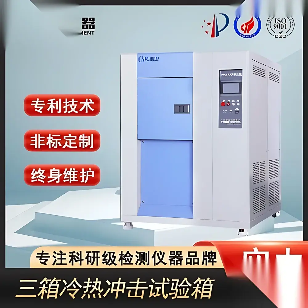
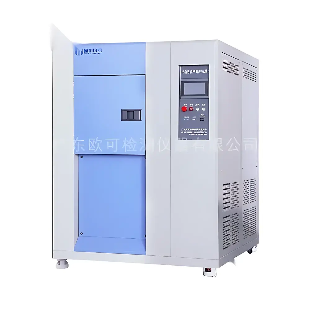
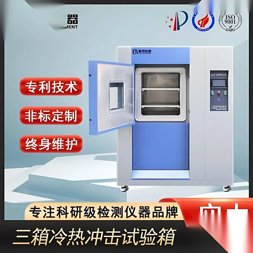
| Construction | SUS304 stainless steel inner chamber, A3 steel outer shell with powder coating |
| Viewing Window | Reinforced heated tempered glass with LED lighting |
| Test Port | Ø50 mm on left side |
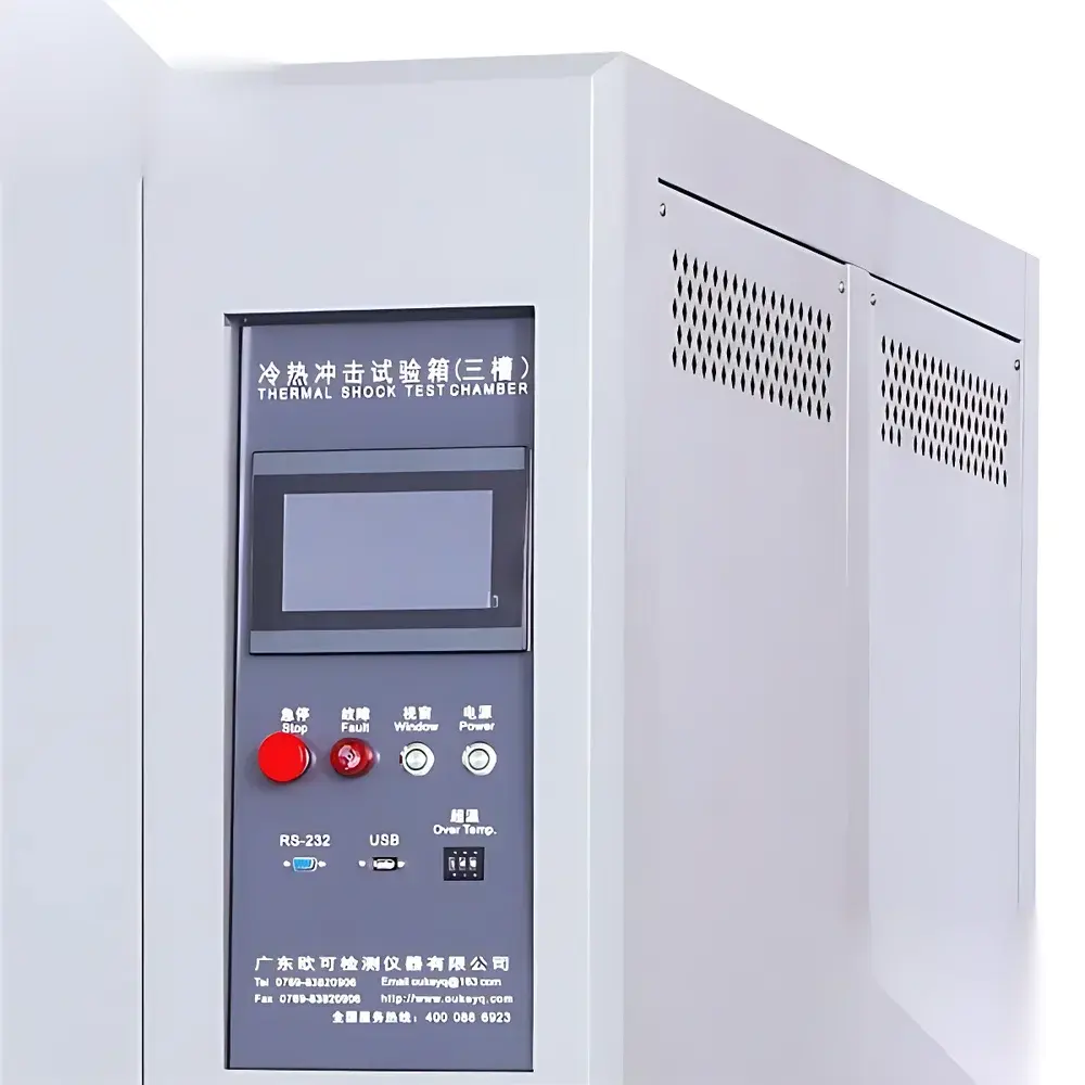
| Controller | Touchscreen PID temperature controller with parameter lock and auto-tuning |
| Refrigeration | Dual-stage or single-stage cascade system with Tecumseh (France) compressors, Acro (USA) dry filters, Guanya (Taiwan) oil separators, Castel (Italy) solenoid valves |
| Air Circulation | Multi-wing centrifugal blower with optimized inlet/outlet duct design for uniform thermal distribution and rapid recovery (<5 min after door opening) |
Overview
The Thermal Shock Test Chamber series (TS-80 through OK-TS-1000) is an engineered environmental stress screening (ESS) system designed for accelerated reliability validation of electronic components, automotive modules, optoelectronic devices, and precision electromechanical assemblies under extreme thermal transition conditions. Operating on the principle of rapid, high-fidelity temperature cycling between two independently controlled chambers — a high-temperature zone (typically +150 °C) and a low-temperature zone (typically −70 °C) — the system subjects test specimens to abrupt thermal gradients that replicate field-induced mechanical fatigue in solder joints, conformal coatings, encapsulants, and heterogeneous material interfaces. Unlike steady-state thermal chambers, this dual-zone architecture enables programmable dwell times, transfer times (≤15 s), and cycle counts compliant with MIL-STD-810H Method 503.7, IEC 60068-2-14, JESD22-A104E, and IPC-9701A standards. Its robust mechanical construction and calibrated thermal response ensure repeatable shock profiles across qualification, lot acceptance, and failure analysis workflows.
Key Features
- High-precision dual-chamber architecture with independent heating/cooling circuits for rapid thermal transitions (typical transfer time ≤12 s)
- SUS304 mirror-finish interior chamber and A3 steel exterior with electrostatic powder coating for corrosion resistance and cleanroom compatibility
- Heated, laminated tempered glass observation window with integrated LED illumination for real-time visual monitoring without thermal leakage
- Standard Ø50 mm cable/port access on left wall, sealed with silicone gasket and configurable with optional feedthrough connectors (e.g., thermocouple, power, Ethernet)
- Industrial-grade touchscreen controller with PID auto-tuning, parameter locking, data logging (up to 10,000 cycles), and USB export capability
- Cascade refrigeration system utilizing Tecumseh hermetic compressors, Acro desiccant filters, Guanya oil separators, and Castel solenoid valves for long-term stability and low maintenance
- Multi-blade centrifugal circulation fan with asymmetric duct geometry ensuring ±0.5 °C uniformity (at 100 mm from chamber walls) and <5 min temperature recovery post-door-opening
Sample Compatibility & Compliance
This chamber accommodates a broad spectrum of physical form factors — from surface-mount PCBs and bare die carriers to assembled ECUs, LED arrays, fiber optic transceivers, and automotive wiring harnesses. Internal dimensions range from 400×450×400 mm (TS-80, 80 L net volume) to 1000×1000×1000 mm (OK-TS-1000, 1000 L), supporting standard test trays, dunnage fixtures, and custom load racks. All models are designed and verified per IEC 61000-4-27 (electromagnetic immunity during thermal transients), UL 61010-1 (safety), and ISO/IEC 17025 traceable calibration protocols. The control firmware supports audit-ready operation logs, user-level access control, and optional 21 CFR Part 11-compliant electronic signatures when integrated with validated LIMS environments.
Software & Data Management
Embedded controller firmware provides real-time graphical display of chamber setpoints, actual temperatures (hot/cold zones + specimen interface), cycle count, elapsed time, and alarm history. Data is stored internally with timestamped CSV export via USB 2.0. Optional PC-based software (Windows 10/11 compatible) enables remote monitoring, multi-chamber fleet management, automated report generation (PDF/Excel), and integration with MES systems via Modbus TCP or OPC UA. All logged thermal profiles include metadata such as operator ID, test plan revision, calibration certificate number, and environmental ambient conditions — fulfilling GLP and GMP documentation requirements for regulated industries.
Applications
- Qualification testing of solder joint integrity per IPC-J-STD-002 and IPC-SM-785
- Accelerated life testing of polymer-based insulators, potting compounds, and conformal coatings
- Failure mode analysis (FMA) of MEMS sensors, RF front-end modules, and power semiconductor packages
- Reliability screening for aerospace avionics per RTCA/DO-160 Section 24 (Temperature Shock)
- Validation of thermal expansion coefficient mismatch in hybrid packaging (e.g., SiC-on-Si, GaN HEMTs)
- Stress screening of medical device PCBAs prior to ISO 13485 certification audits
FAQ
What is the typical temperature transition time between hot and cold zones?
Transition time is programmable and typically ranges from 10 to 15 seconds, depending on chamber size and selected temperature extremes.
Can the chamber operate with nitrogen purge for oxygen-sensitive samples?
Yes — all models support optional inert gas purging via mass flow controller (MFC)-regulated inlet port, with pressure monitoring and interlock safety logic.
Is third-party calibration certification included with delivery?
Factory calibration with NIST-traceable reference probes is provided; ISO/IEC 17025-accredited calibration certificates are available as an add-on service.
How is thermal uniformity validated across the working volume?
Uniformity is verified using a 9-point sensor array per IEC 60068-3-5, with results documented in the commissioning report showing deviation ≤±0.8 °C at steady state.
Does the system meet CE marking requirements for EU deployment?
Yes — fully compliant with EMC Directive 2014/30/EU, Low Voltage Directive 2014/35/EU, and RoHS 2011/65/EU, with Declaration of Conformity supplied.

")

