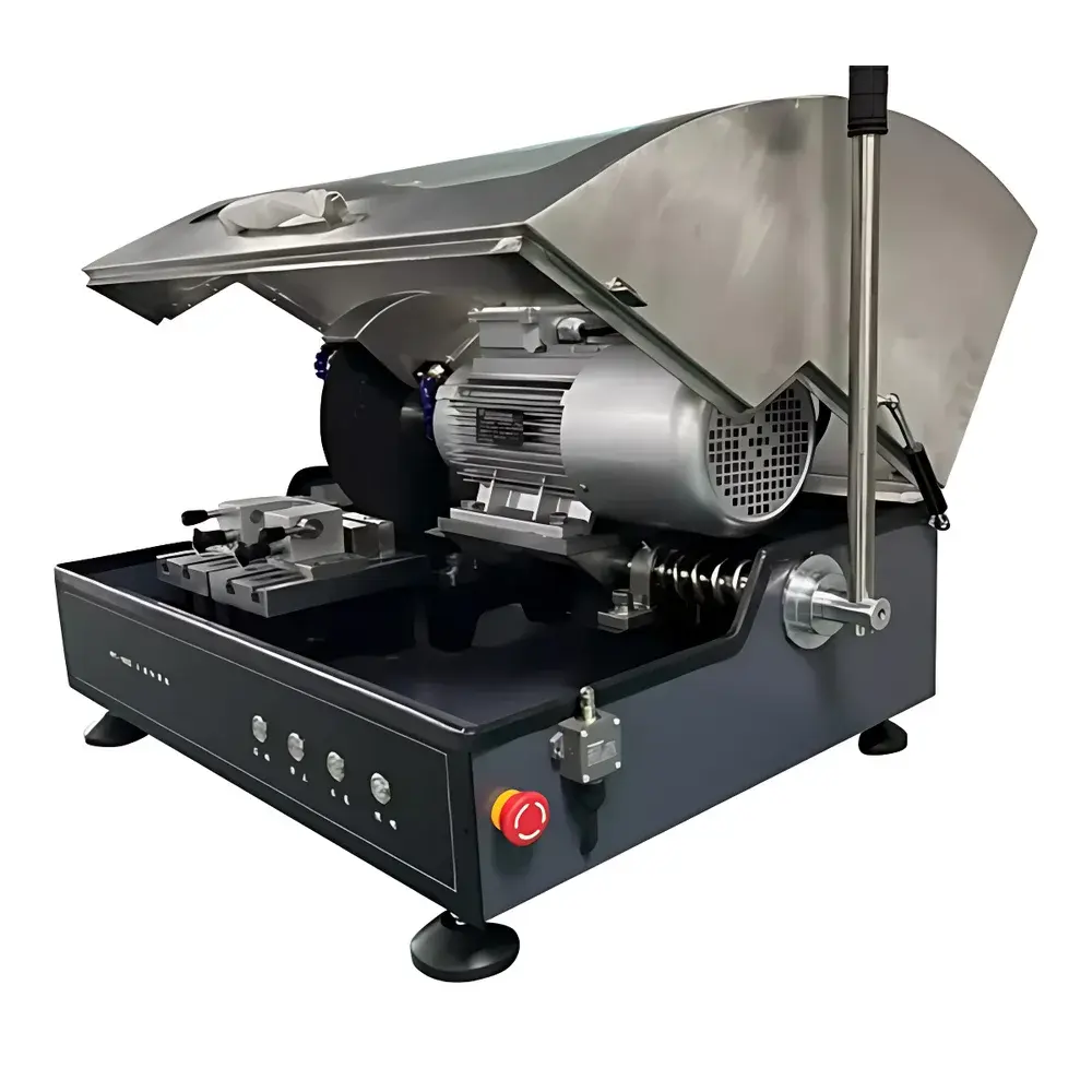
WEIYEE Q-100S/Q-80S Desktop Metallographic Cutting Machine
| Brand | WEIYEE |
|---|---|
| Origin | Guangdong, China |
| Model | Q-100S / Q-80S |
| Max Cutting Diameter | Φ100 mm (Q-100S) / Φ80 mm (Q-80S) |
| Power Supply | 380 V AC, 3 kW |
| Motor Brake System | Integrated electromagnetic brake |
| Cooling System | Closed-loop recirculating water cooling (30 L reservoir) |
| Cutting Wheel Dimensions | Φ300 × 32 × 2.0 mm |
| Instrument Type | Metallographic Cutting Machine |
| Compliance | Designed for ISO 5725-based precision sample sectioning in metallurgical labs |
Overview
The WEIYEE Q-100S and Q-80S are precision-engineered desktop metallographic cutting machines designed for controlled, repeatable cross-sectional preparation of metallic, ceramic, and composite specimens prior to mounting, grinding, and polishing. These instruments operate on the principle of high-torque abrasive wheel cutting under continuous, regulated coolant flow—ensuring minimal thermal distortion, reduced microstructural artifacts (e.g., phase transformation or edge smearing), and preservation of the original grain structure at the cut interface. Unlike open-loop benchtop saws, the Q-series features a fully enclosed cutting chamber with interlocked safety doors, meeting fundamental mechanical hazard requirements per EN 692 (Machine Safety – Presses) and aligning with laboratory risk mitigation protocols for ISO/IEC 17025-accredited testing facilities. The integrated electromagnetic brake enables rapid spindle stop within ≤1.2 seconds after command cutoff—critical for operator safety during emergency interventions or routine specimen handling.
Key Features
- Two model variants optimized for workflow scalability: Q-100S supports specimens up to Φ100 mm diameter; Q-80S accommodates up to Φ80 mm—both compatible with standard ISO 4497-compliant metallographic blanks and ASTM E3-22 reference test blocks.
- High-efficiency 3 kW three-phase motor delivering stable rotational speed (typically 2,850 rpm nominal) across variable load conditions—maintaining consistent wheel surface velocity for uniform material removal rates.
- Closed-loop recirculating cooling system with 30 L polyethylene reservoir, adjustable flow control valve, and integrated temperature sensor—enabling precise thermal management to prevent localized overheating (>60 °C threshold) that may induce martensitic transformation in hardened steels or intergranular oxidation in nickel alloys.
- Standardized arbor configuration accepts industry-standard Φ300 × 32 × 2.0 mm reinforced resin-bonded silicon carbide or diamond-impregnated cutting wheels (ISO 6344-2 compliant), with optional quick-change flange kits available for wheel diameter adaptation.
- Robust cast-iron base frame with vibration-damping feet ensures dimensional stability during high-force sectioning of cast iron, tool steel, or tungsten carbide inserts—reducing runout deviation to <0.05 mm over full stroke travel.
Sample Compatibility & Compliance
The Q-100S/Q-80S is validated for sectioning ferrous and non-ferrous metals (including austenitic stainless steels, aluminum alloys, titanium Grade 5), sintered ceramics (Al₂O₃, SiC), and fiber-reinforced polymer composites. Specimen clamping utilizes dual-axis mechanical vise with T-slot base plate (M6 threaded holes), accommodating irregular geometries via custom fixture integration. All operational parameters—including feed rate (manual micrometer adjustment), cutting depth (0–50 mm range), and coolant pressure (0.1–0.3 MPa)—are documented in the device’s traceable calibration log. The system conforms to essential requirements of IEC 61000-6-2 (immunity) and IEC 61000-6-4 (emission), and supports GLP-aligned documentation when paired with external lab information management systems (LIMS).
Software & Data Management
While the Q-100S/Q-80S operates via analog/manual controls (no embedded microprocessor or touchscreen interface), it includes standardized RS-232 and dry-contact I/O ports for integration into automated sample prep workflows. Optional digital retrofit modules enable logging of cycle start/stop timestamps, total runtime, and coolant temperature history—exportable as CSV files compliant with FDA 21 CFR Part 11 audit trail requirements when used in GMP-regulated environments (e.g., aerospace component QA or medical implant material certification). Calibration certificates and maintenance records follow ISO/IEC 17025 Clause 6.4.10 documentation standards.
Applications
- Precision sectioning of tensile bars, fatigue test coupons, and weld cross-sections per ASTM E8/E8M and ISO 6892-1.
- Preparation of representative samples for subsequent SEM-EDS analysis, electron backscatter diffraction (EBSD), or quantitative metallography per ASTM E112 and ISO 643.
- Routine quality control in foundries, heat treatment facilities, and additive manufacturing post-processing lines—supporting microstructure verification against AMS 2300, NADCAP AC7101, and GE B50TF12 specifications.
- Academic research in physical metallurgy, including phase transformation studies requiring artifact-free interfaces for dilatometry correlation.
FAQ
What types of cutting wheels are compatible with the Q-100S/Q-80S?
Standard Φ300 × 32 × 2.0 mm wheels with 32 mm bore and ISO 6344-2-compliant bonding matrix (resinoid or vitrified) are supported. Diamond-impregnated variants require confirmation of maximum peripheral speed rating ≥45 m/s.
Is the machine suitable for cutting hardened tool steels (HRC >60)?
Yes—when used with diamond wheels and maintained coolant flow ≥3.5 L/min, the system achieves reproducible sectioning of D2, M2, and H13 tool steels without edge chipping or subsurface cracking.
Does the unit include CE or UL certification?
The base configuration meets EMC and LVD requirements per EU Directive 2014/30/EU and 2014/35/EU; third-party CE marking documentation is available upon request for export compliance.
Can the coolant system be connected to a centralized lab chiller?
Yes—the inlet/outlet ports accept 1/2″ BSP threaded connections; external pressure regulation is recommended to maintain 0.15–0.25 MPa supply pressure.
What is the typical maintenance interval for the electromagnetic brake assembly?
Brake coil resistance and contactor response time should be verified every 500 operating hours or quarterly—whichever occurs first—per manufacturer’s preventive maintenance schedule (P/N WM-Q-BRK-PM-2023).


