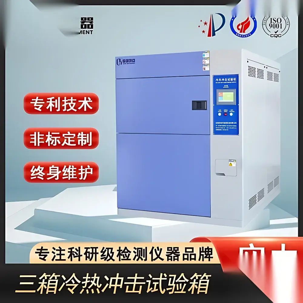
Three-Chamber Thermal Shock Test Chamber
| Brand | Other Brands |
|---|---|
| Origin | Imported |
| Manufacturer Type | General Distributor |
| Price | USD 11,200 (approx.) |
Overview
The Three-Chamber Thermal Shock Test Chamber is an engineered environmental test system designed to evaluate material and component reliability under rapid, repetitive transitions between extreme high-temperature, low-temperature, and ambient-temperature conditions. Unlike two-chamber designs that rely on mechanical transfer of test specimens, this configuration employs three physically isolated chambers: a high-temperature chamber (typically up to +150 °C), a low-temperature chamber (down to –70 °C), and a central test chamber where the specimen remains stationary throughout the test cycle. Temperature shock is induced by opening/closing pneumatically actuated insulated doors—allowing controlled thermal gas exchange while eliminating mechanical stress from specimen movement. This architecture ensures high reproducibility in thermal transient profiles and supports continuous monitoring of sensitive electronic signals (e.g., voltage, resistance, or thermocouple outputs) via dedicated feedthrough ports. The system operates with defined dwell periods at each temperature extreme and at ambient (typically 25 °C), producing temperature-time profiles approximating sinusoidal transitions due to thermal mass inertia and PID-controlled heating/cooling dynamics.
Key Features
- Stationary specimen design: Eliminates mechanical shock, vibration, and positional error—critical for PCB assemblies, MEMS devices, and optoelectronic modules.
- Triple-chamber architecture: Independent high-temperature (+150 °C max), low-temperature (–70 °C min), and ambient test zones with sealed door interlocks and thermal break insulation.
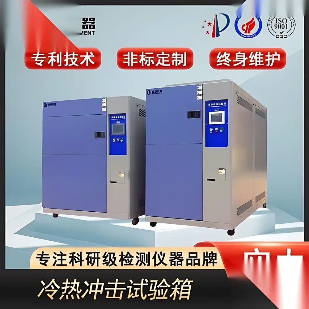
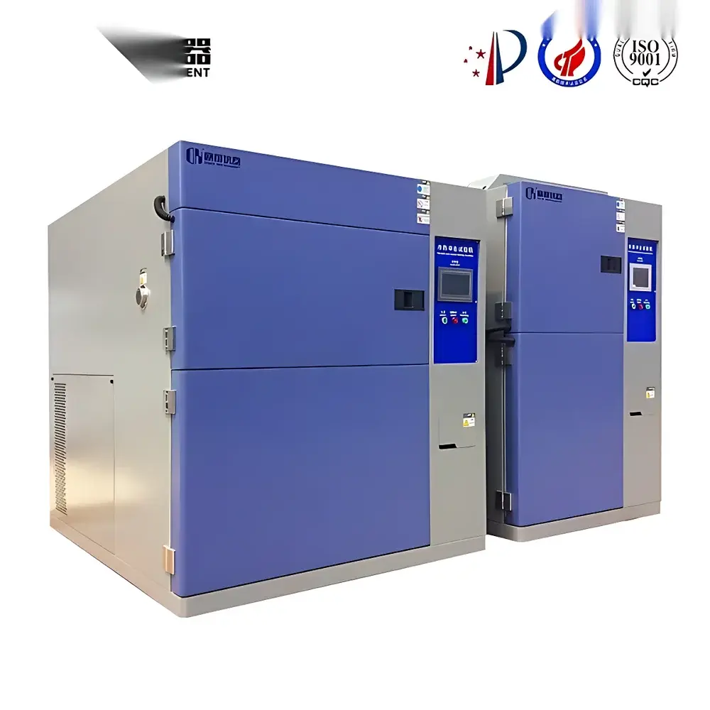
- Configurable chamber materials: Standard options include electropolished stainless steel (AISI 304) for corrosion resistance and cleanroom compatibility, or powder-coated cold-rolled steel with customizable RAL color matching.
- Structural integrity: 1.2 mm thick inner chamber walls and reinforced frame construction prevent thermal warping under full-load operation and prolonged exposure to thermal extremes.
- Validated internal volume compliance: Internal test chamber dimensions strictly conform to IEC 60068-2-14 and MIL-STD-810H requirements—ensuring specimens are fully immersed within the designated test zone, not positioned in airflow ducts or boundary regions.
- Thermal transition control: Programmable dwell times (1–999 minutes per stage), ramp rate modulation, and automatic ambient stabilization prior to specimen loading/unloading.
Sample Compatibility & Compliance
This chamber accommodates specimens ranging from small semiconductor packages to large automotive ECUs or aerospace avionics enclosures. Standard internal volumes include 50 L, 80 L, 100 L, 150 L, 225 L, 408 L, 800 L, and 1000 L—selected based on maximum projected specimen envelope plus required air clearance (≥15% free volume per IEC 60068-3-5). The system meets essential compliance benchmarks including IEC 60068-2-14 (Change of temperature), ASTM D5229/D5229M (Low-temperature impact performance), and JESD22-A104 (Temperature cycling). Optional calibration traceability to NIST standards and documentation packages support GLP/GMP validation protocols and FDA 21 CFR Part 11–compliant audit trails when integrated with certified data acquisition software.
Software & Data Management
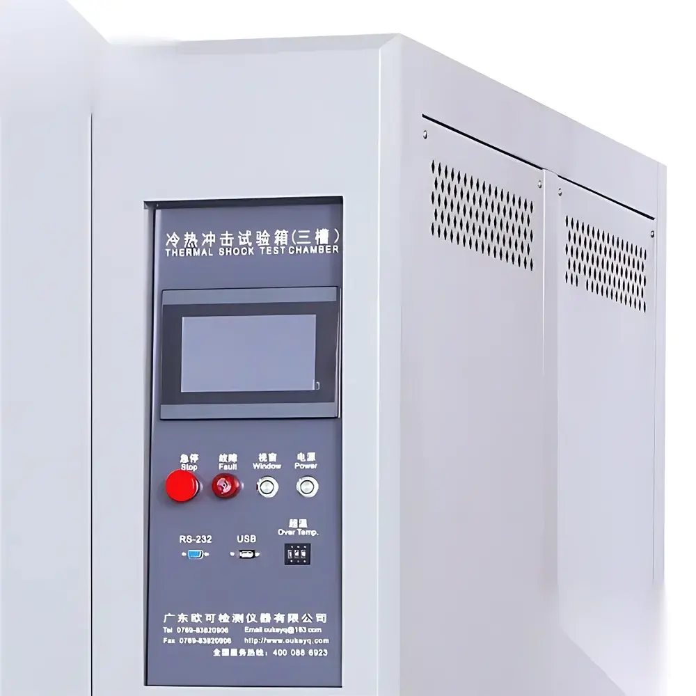
Equipped with a 10.1″ capacitive touchscreen HMI running embedded Linux, the controller provides real-time graphical display of chamber temperatures, door status, alarm history, and cycle progress. Test programs are created using ISO/IEC 17025-aligned parameter templates—including up to 999 steps, conditional branching, and user-defined pass/fail criteria. Data logging records all sensor inputs (Pt100 RTDs, thermocouples) at configurable intervals (1–60 seconds), stored internally (32 GB SSD) and exportable via USB or Ethernet (Modbus TCP, OPC UA). Optional PC-based software enables remote supervision, automated report generation (PDF/CSV), statistical process control (SPC) charting, and integration into enterprise LIMS or MES platforms.
Applications
- Qualification testing of solder joints, conformal coatings, and underfill materials per IPC-9701 and JEDEC J-STD-020.
- Reliability screening of battery cells and BMS modules under accelerated thermal aging conditions.
- Validation of hermetic seals in medical implant housings per ISO 11607-2.
- Thermal fatigue assessment of ceramic substrates, LED packages, and power modules used in EV inverters.
- Environmental stress screening (ESS) of avionics components compliant with DO-160 Section 4.11.
- Material coefficient-of-thermal-expansion (CTE) mismatch analysis in multi-layer packaging structures.
FAQ
What distinguishes a three-chamber thermal shock chamber from a two-chamber system?
The three-chamber design maintains specimen immobility—eliminating acceleration-induced failure modes and enabling uninterrupted electrical signal monitoring during transitions.
Why is internal chamber wall thickness specified as 1.2 mm?
Thickness ensures dimensional stability across repeated thermal cycles; thinner panels (<1.0 mm) risk buckling under thermal gradient stress and compromise temperature uniformity per IEC 60068-3-5 Annex A.
Can this chamber meet MIL-STD-810H Method 503.5 requirements?
Yes—when configured with appropriate temperature ranges (e.g., –55 °C to +150 °C), dwell times ≥20 min, and transition times ≤15 seconds (achievable with optional high-capacity refrigeration and auxiliary heaters).
Is ambient-temperature dwell mandatory in thermal shock testing?
Not universally—but it is required for standards such as IEC 60068-2-14 Clause 6.3 (Method Na) and supports realistic simulation of operational storage-to-use thermal transients.
How is temperature uniformity validated inside the test chamber?
Per IEC 60068-3-5, a minimum of nine PT100 sensors are placed in a 3×3 grid at the center plane of the test volume; deviation must remain within ±2 °C during steady-state dwell at any setpoint.


")
