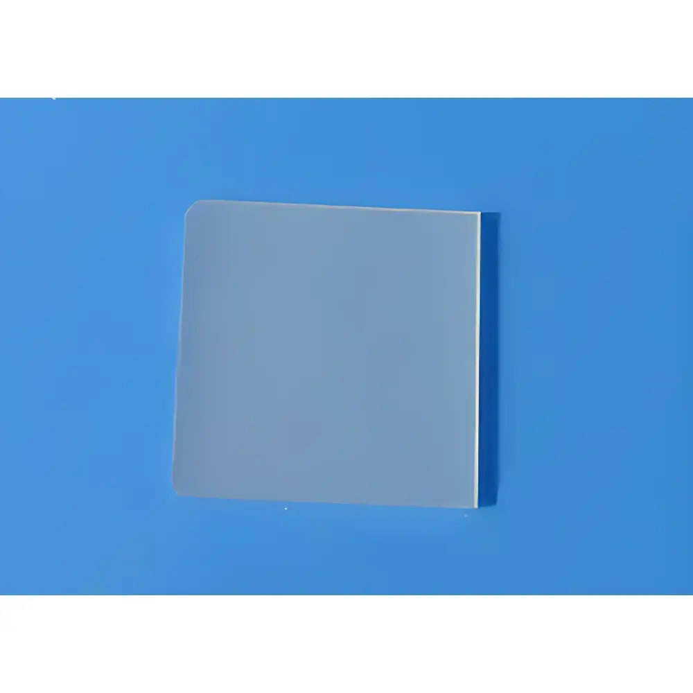
TbScO₃ Single Crystal Substrate Wafers
| Brand | Hefei Kejing |
|---|---|
| Origin | Anhui, China |
| Manufacturer Type | Authorized Distributor |
| Origin Category | Domestic (PRC) |
| Model | TbScO₃ Single Crystal Substrate |
| Price | Upon Request |
| Crystal Structure | Orthorhombic (Space Group: Pbnm) |
| Lattice Parameters | a ≈ 5.52 Å, b ≈ 5.70 Å, c ≈ 7.88 Å |
| Melting Point | ~2120 °C |
| Density | ~6.8 g/cm³ |
| Growth Method | Czochralski (Cz) |
| Orientation | <110> ± 0.5° |
| Dimensions | 10 × 10 × 0.5 mm³ or 5 × 5 × 0.5 mm³ |
| Surface Finish | Single-side polished |
| Surface Roughness (Ra) | < 0.5 nm |
| Packaging | Vacuum-sealed in Class 100 cleanroom bags, stored and shipped from Class 1000 cleanroom environment |
Overview
TbScO₃ (terbium scandium oxide) single crystal substrates are engineered orthorhombic perovskite-structured oxides with exceptional lattice matching to high-Tc cuprate superconductors—including YBCO (YBa₂Cu₃O7−δ) and LSCO (La2−xSrxCuO4)—as well as ferroelectric and multiferroic thin films such as BiFeO₃, Pb(Zr,Ti)O₃ (PZT), and EuO. The near-ideal epitaxial match (lattice mismatch < 0.5% for (110)TbScO3//(001)YBCO) enables atomically coherent heteroepitaxy, minimizing interfacial strain and defect generation during pulsed laser deposition (PLD), molecular beam epitaxy (MBE), or sputtering. Unlike conventional SrTiO₃ or LaAlO₃ substrates, TbScO₃ exhibits intrinsic chemical stability under reducing atmospheres and elevated oxygen partial pressures, making it suitable for in situ growth of oxide heterostructures requiring precise stoichiometric control. Its moderate dielectric constant (εr ≈ 28–32 at 1 MHz) and low loss tangent (tan δ < 0.002) further support high-fidelity electrical characterization of interfacial transport phenomena.
Key Features
- High-purity single-crystal wafers grown via optimized Czochralski method under controlled oxygen partial pressure, ensuring stoichiometric Tb/Sc ratio and minimal point defects
- Precise crystallographic orientation with angular tolerance ≤ ±0.5°, verified by high-resolution X-ray diffraction (HR-XRD) rocking curve analysis (FWHM < 0.03°)
- Single-side polished surface with root-mean-square roughness Ra < 0.5 nm, confirmed by atomic force microscopy (AFM) over 5 × 5 µm² scan areas
- Thermal expansion coefficient (25–800 °C): α ≈ 10.2 × 10⁻⁶ K⁻¹ (a-axis), 11.8 × 10⁻⁶ K⁻¹ (b-axis), 14.5 × 10⁻⁶ K⁻¹ (c-axis), enabling compatibility with thermal cycling in UHV deposition systems
- Chemically inert surface resistant to standard RCA cleaning (NH₄OH:H₂O₂:H₂O and HCl:H₂O₂:H₂O), HF-free etching, and ozone exposure
- Batch-certified with full traceability: each wafer lot includes HR-XRD θ–2θ scans, rocking curves, AFM topographs, and EDX compositional maps
Sample Compatibility & Compliance
TbScO₃ substrates are routinely employed in laboratories operating under ISO/IEC 17025-accredited quality management systems and comply with materials handling requirements outlined in ASTM F1529 (Standard Guide for Use of Epitaxial Substrates in Semiconductor Device Fabrication). While not classified as medical devices or regulated under FDA 21 CFR Part 11, documentation packages support GLP-compliant thin-film process development—particularly for academic and industrial research into oxide electronics, spintronics, and quantum interface engineering. All substrates are fabricated and packaged in ISO Class 6 (1000) cleanrooms; final vacuum sealing occurs in ISO Class 5 (100) laminar flow hoods. Certificate of Analysis includes batch-specific lattice parameter verification, surface contamination screening (via TOF-SIMS), and particulate count data (per ISO 14644-1).
Software & Data Management
No embedded firmware or proprietary software is associated with TbScO₃ substrates, as they are passive crystalline platforms. However, integration into automated thin-film synthesis workflows (e.g., Oxford Instruments IonFab, SPECS GmbH QAS systems) is facilitated by standardized substrate cassette formats (e.g., 25-mm diameter carriers compatible with 4-inch wafer handling robotics). Digital records—including XRD metadata, AFM image stacks, and EDX spectra—are delivered in vendor-neutral formats (TIFF, CSV, .xy) compatible with common scientific data management systems (e.g., LabArchives, eLabFTW) and FAIR-aligned repositories. Optional custom labeling (QR-coded lot IDs) supports traceability across multi-institutional projects governed by Horizon Europe or DOE-funded collaborative agreements.
Applications
- Epitaxial growth of high-temperature superconducting YBCO films for microwave resonators and Josephson junction arrays
- Template layers for strain-engineered ferroelectric tunnel junctions (FTJs) and magnetoelectric heterostructures
- Substrates for in situ angle-resolved photoemission spectroscopy (ARPES) of correlated electron systems
- Platform for studying interfacial charge transfer and orbital reconstruction in complex oxide interfaces (e.g., LaAlO₃/TbScO₃)
- Reference substrates in inter-laboratory round-robin studies on oxide thin-film nucleation kinetics (coordinated under IUPAC Division VIII)
- Calibration standards for synchrotron-based coherent diffraction imaging (CDI) of domain structures in multiferroics
FAQ
What is the typical off-cut tolerance for the orientation?
The angular deviation from nominal is guaranteed within ±0.5°, measured using a four-circle diffractometer with Cu-Kα radiation and Si (111) reference standard.
Can these substrates be reused after thin-film growth?
Reuse is not recommended due to irreversible surface reconstruction, interdiffusion, or residual metal adatoms; however, post-growth annealing in O₂ at 700 °C may restore surface order for limited recharacterization.
Is there batch-to-batch variation in lattice parameters?
Lattice parameter variation across production lots is maintained within ±0.003 Å (3σ), as monitored by daily calibration against NIST SRM 640d Si powder standard.
Do you provide substrates with conductive backside metallization?
Standard offerings are unmetallized; custom Au/Ti or Pt/Ti backside sputtering is available upon request with additional lead time and qualification testing.
Are TEM-ready cross-section samples available?
Yes—focused ion beam (FIB) lift-out specimens prepared from bonded TbScO₃/Si heterostructures can be supplied with pre-characterized thickness uniformity (±5 nm) and amorphous layer minimization protocols.