YANRUN ZQ-300F Intelligent Fully Automatic Metallographic Cutting Machine
| Brand | YANRUN |
|---|---|
| Origin | Shanghai, China |
| Manufacturer Type | Direct Manufacturer |
| Equipment Type | Metallographic Cutting Machine |
| Model | ZQ-300F |
| Cutting Mode | Vertical / Layered / Horizontal / Coordinated 3-Axis (X/Y/Z) Cutting |
| Max. Cutting Diameter | 120 mm |
| Max. Disc Workpiece Size | 300 × 100 mm (OD × Height) |
| Spindle Speed | 100–3000 rpm (Infinitely Variable) |
| X-Axis Travel | 50 mm (Motorized) |
| X-Axis Speed | 0–100 mm/min (Infinitely Variable) |
| Y-Axis Travel | 200 mm (Motorized) |
| Y-Axis Speed | 0–200 mm/min (Infinitely Variable) |
| Z-Axis Stroke | 200 mm |
| Z-Axis Speed | 0–200 mm/min (Infinitely Variable) |
| Cutting Feed Rate | 1–200 mm/min |
| Effective Cutting Depth | 150 + 200 mm |
| Cutting Table Dimensions | 650 × 300 mm (Stainless Steel) |
| Standard Blade Size | Ø250–380 × 1.5–2.5 × 32 mm |
| Cooling System | 4-Channel Automated Water Cooling with Optional Magnetic Separation |
| Coolant Tank Capacity | 60 L |
| Motor Power | 5.5 kW |
| Power Supply | 380 V AC |
| Machine Weight | 500 kg |
| Control Interface | 8-inch Color Touchscreen + PLC-Based Motion Control |
| Compliance | Designed for ISO 14971 Risk Management and ASTM E3-22 Sample Preparation Standards |
Overview
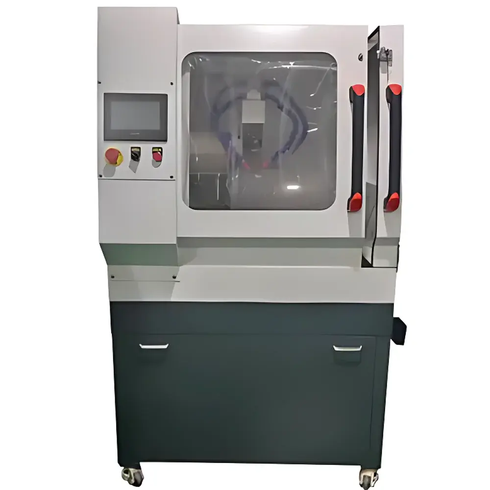
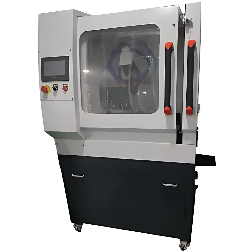
The YANRUN ZQ-300F Intelligent Fully Automatic Metallographic Cutting Machine is an industrial-grade, floor-standing precision sample preparation system engineered for reproducible, high-fidelity sectioning of metallic and composite specimens in metallurgical, automotive, foundry, and advanced materials R&D laboratories. Based on a rigid three-axis (X/Y/Z) coordinated motion architecture, the ZQ-300F implements deterministic kinematic control to execute complex cutting trajectories—including vertical sectioning, layered slicing, horizontal profiling, and synchronized multi-directional feed—without manual intervention. Unlike conventional single-axis cutters, its integrated servo-driven axes enable programmable depth-of-cut, variable feed rates, and real-time positional feedback, making it suitable for irregular geometries such as cast engine blocks, turbine blades, brake calipers, and additively manufactured components where precise orientation and minimal thermal distortion are critical. The machine operates under controlled coolant delivery and adheres to core principles of metallographic best practices defined in ASTM E3-22 and ISO 14971, ensuring that cut surfaces maintain structural integrity prior to mounting, grinding, and polishing.
Key Features
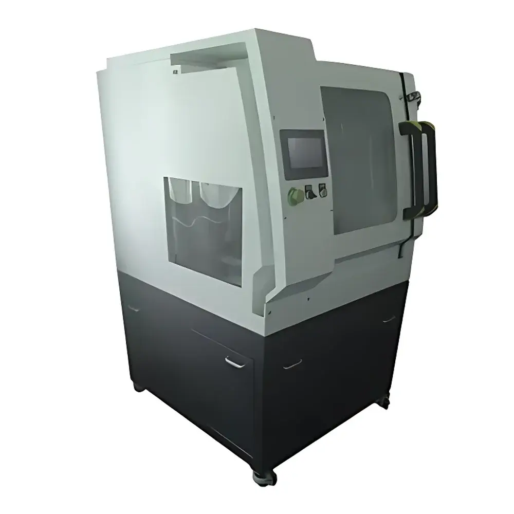
- Floor-mounted monolithic frame with vibration-damped base structure for enhanced dimensional stability during high-torque cutting
- Three-axis motorized motion system (X: ±50 mm; Y: ±200 mm; Z: 200 mm stroke) with independent speed control (0–200 mm/min) and position repeatability ≤ ±0.02 mm
- Infinitely variable spindle speed (100–3000 rpm) optimized for diverse abrasive wheel types (e.g., resin-bonded SiC, diamond-impregnated, or alumina) and material hardness ranges (HB 100–650)
- Transparent front-access cutting chamber with full-height polycarbonate shielding, enabling real-time visual monitoring without interrupting operation
- Programmable multi-stage cutting cycles: user-defined start/stop positions, dwell times, feed acceleration profiles, and automatic tool retraction sequences
- Integrated 8-inch color touchscreen HMI with PLC-based logic controller supporting G-code-like macro programming and password-protected parameter locking
- Automated 4-channel water-cooling system with adjustable flow distribution and optional magnetic separator module for ferrous debris removal from recirculated coolant
- Stainless steel cutting table (650 × 300 mm) with modular dual-layer clamping platform accommodating both standard vise fixtures and custom jig adapters
Sample Compatibility & Compliance
The ZQ-300F accommodates specimens up to Ø120 mm in diameter or 300 × 100 mm in disc format, including non-uniform shapes requiring angular alignment or offset sectioning. Its open-through chamber design permits longitudinal cutting of elongated components (e.g., shafts, rods, or extrusions) exceeding standard benchtop capacity. The system supports common metallographic standards for specimen integrity: ASTM E3-22 (Standard Guide for Preparation of Metallographic Specimens), ISO 643 (Steel – Micrographic Determination of Ferrite Content), and EN 10365 (Metallic Materials – Metallographic Examination). All electrical and mechanical subsystems comply with CE machinery directive (2006/42/EC) and IEC 60204-1 safety requirements. Optional audit trail logging and electronic signature functionality align with GLP/GMP documentation workflows per FDA 21 CFR Part 11 when integrated with validated LIMS interfaces.
Software & Data Management
The embedded control firmware provides persistent storage of up to 200 user-defined cutting protocols, each configurable with up to 10 sequential motion segments. Each protocol records timestamped operational metadata—including actual spindle RPM, feed rate deviation, coolant pressure, cycle duration, and final position—exportable via USB to CSV for QA traceability. Firmware supports firmware-over-the-air (FOTA) updates through secure HTTPS endpoints. No proprietary software installation is required on host PCs; configuration and diagnostics are accessible via standard web browser using built-in HTTP server (IPv4 only). Audit logs include operator ID, session start/end timestamps, parameter modifications, and emergency stop events—structured to support internal quality audits and regulatory inspections.
Applications
- Precision cross-sectioning of automotive powertrain components (cylinder heads, crankshafts, differential housings) for porosity and inclusion analysis
- Controlled layer-by-layer removal from investment-cast turbine vanes to expose interdendritic microstructure without phase transformation artifacts
- High-accuracy thin-sectioning of weld joints (butt, T-joint, overlay cladding) for fusion zone characterization per AWS D1.1
- Preparation of representative coupons from additively manufactured Ti-6Al-4V or Inconel 718 parts for EBSD and TEM lamella extraction
- Routine batch cutting of QC samples in foundry environments where dimensional consistency across hundreds of castings must be verified per ISO 8062
FAQ
What types of abrasive wheels are compatible with the ZQ-300F?
Standard wheel dimensions range from Ø250–380 mm in diameter, 1.5–2.5 mm thickness, and 32 mm arbor hole. Compatible bonds include resinoid, vitrified, and metal-bonded diamond wheels rated for maximum peripheral speeds ≥ 80 m/s.
Does the machine support automated workflow integration with laboratory information systems?
Yes—via optional RS-485 Modbus RTU or Ethernet/IP interface, enabling bidirectional communication with LIMS or MES platforms for job dispatch, status reporting, and digital log synchronization.
Is remote diagnostics available?
Built-in diagnostic mode generates self-test reports for axis encoder feedback, coolant pump pressure sensors, spindle motor current draw, and thermal protection thresholds—all accessible via HMI or exported to service technician portals.
Can the ZQ-300F perform angled cuts or bevel sectioning?
While the base configuration supports orthogonal X/Y/Z motion only, optional tilting vise modules (sold separately) allow ±15° rotational adjustment of the specimen relative to the blade plane, enabling controlled bevel angle preparation.
What maintenance intervals are recommended for long-term reliability?
Lubrication of linear guide rails every 500 operating hours; spindle bearing inspection every 3,000 hours; coolant filter replacement every 200 cycles or quarterly—whichever occurs first. Full service manuals and spare parts catalogs are provided with each unit.


