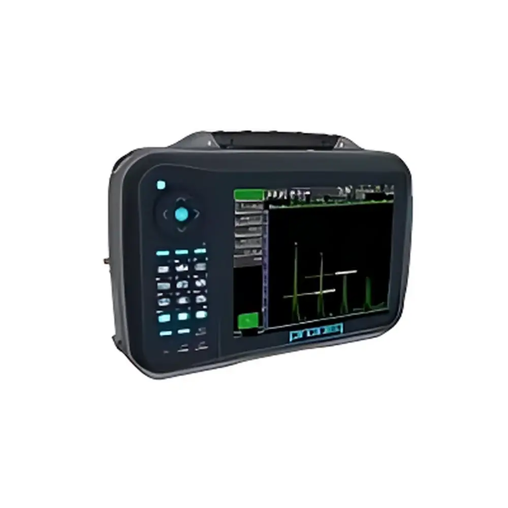
Proceq Flaw Detector 100 UT Ultrasonic Flaw Detector
| Brand | Proceq |
|---|---|
| Model | Flaw Detector 100 |
| Detection Principle | Pulse-Echo & Through-Transmission Ultrasonics |
| Channels | 2 UT channels |
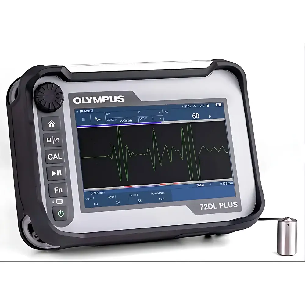
| Display | High-resolution color LCD with dual A-scan display |
| Gain Range | 100 dB (0.1 dB step) |
| Frequency Bandwidth | 200 kHz – 20 MHz |
| Measurement Modes | Path Length, Depth, Surface Distance, DAC, AWS D1.1, DGS/AVG |
| Encoder Support | Dual-axis encoder input for positional data logging |
| Software Platform | 3D Scan™ workflow engine with guided file analysis |
| Reporting | Automated report generation with embedded traceability metadata |
| Upgrade Path | Field-upgradable to TOFD and Phased Array (PA) via firmware license |
Overview
The Proceq Flaw Detector 100 UT is a portable, dual-channel ultrasonic flaw detector engineered for precision weld inspection, corrosion mapping, and volumetric defect characterization in industrial metal components. It operates on pulse-echo and through-transmission ultrasonic principles, utilizing high-fidelity digitization of echo signals to determine flaw location, size, and orientation relative to the transducer interface. Designed for field-deployable NDT workflows, the instrument integrates time-of-flight diffraction (TOFD)-ready architecture and phased array (PA) compatibility—enabling future expansion without hardware replacement. Its real-time dual A-scan display supports side-by-side comparison of primary and reference waveforms, facilitating rapid interpretation under variable surface conditions or complex geometries. The device complies with core requirements of EN 12668-1 (characteristics and verification of ultrasonic equipment) and ISO 2400 (reference blocks for ultrasonic testing), serving as a compliant platform for inspections governed by ASME BPVC Section V, ASTM E709, and ISO 17640.
Key Features
- Dual independent UT channels with synchronized triggering and full parameter control per channel
- 100 dB gain range adjustable in precise 0.1 dB increments, supporting low-amplitude signal detection in coarse-grained or attenuative materials
- Wide bandwidth operation from 200 kHz to 20 MHz—optimized for both low-frequency thickness gauging in castings and high-resolution flaw sizing in rolled plate
- Integrated dual-axis encoder interface for spatially resolved C-scan reconstruction and automated scan path documentation
- 3D Scan™ software environment enabling intuitive inspection program creation, real-time B/C-scan visualization, and post-processing waveform analysis
- Firmware-based upgrade path to TOFD and phased array modalities—requiring only a licensed activation key, no physical module swap
- Automated reporting engine generating PDF/HTML reports with embedded calibration records, operator ID, timestamped acquisition logs, and measurement uncertainty flags
Sample Compatibility & Compliance
The Flaw Detector 100 UT is validated for use on ferrous and non-ferrous metals including carbon steel, stainless steel, aluminum alloys, titanium, and duplex grades. It accommodates standard 0°, angle-beam (45°–70°), and immersion transducers with LEMO-00 connectors. Surface roughness up to Ra 12.5 µm and curvature radii down to 25 mm are supported with appropriate wedge selection and coupling optimization. The system meets electromagnetic compatibility (EMC) requirements per IEC 61326-1 and carries CE marking for industrial environments. Calibration traceability follows ISO/IEC 17025 guidelines when used with certified reference blocks (e.g., IIW Type I, V1, or ASME Section V Article 4 blocks). Data integrity aligns with ALARP (As Low As Reasonably Practicable) principles and supports GLP/GMP audit readiness via configurable user access levels and electronic signature options.
Software & Data Management
The embedded 3D Scan™ operating system provides a structured workflow—from setup and calibration to scanning, analysis, and reporting. All acquired A-scans are stored with full metadata (gain, delay, velocity, probe ID, date/time, GPS if enabled) in a proprietary but exportable binary format (.pfd). Export options include CSV for amplitude/distance tables, PNG/JPEG for annotated A/B/C-scan images, and XML for integration into enterprise asset management (EAM) or CMMS platforms. Audit trail functionality records all parameter changes, report generations, and firmware updates with immutable timestamps. Optional cloud synchronization enables remote review by Level III personnel and centralized database archiving compliant with ISO 14721 (OAIS) reference models.
Applications
- Weld inspection in pipeline girth welds, pressure vessel circumferential joints, and structural steel connections per AWS D1.1 and API 1104
- Corrosion monitoring in storage tanks and offshore platform legs using depth profiling and remaining wall thickness mapping
- Forging and casting evaluation for internal shrinkage, porosity, and inclusions in aerospace and power generation components
- Clad layer bond integrity assessment via interface echo amplitude and phase analysis
- Pre-service and in-service inspection of rail axle ultrasonic testing programs aligned with EN 1369 and UIC 812-2
- Research-grade material characterization requiring repeatable velocity measurements and attenuation coefficient derivation
FAQ
Is the Flaw Detector 100 UT certified for use in regulated industries such as oil & gas or nuclear?
Yes—it meets essential performance criteria outlined in ISO 10893-1 and EN 13660 for equipment qualification, and its data handling features support compliance with API RP 1163 and NRC Regulatory Guide 1.192 when configured with secure user authentication and audit logging.
Can it perform TOFD inspection out of the box?
No—TOFD capability requires a firmware license activation and compatible TOFD probes/transmitter-receiver modules; however, the base unit includes all necessary timing resolution (<1 ns jitter), digitization rate (100 MS/s), and encoder synchronization infrastructure.
What standards does its DAC curve implementation follow?
DAC curves comply with ASME Section V Article 4 (for ferritic steels) and EN 1714 (welds), supporting multiple reference reflectors (side-drilled holes, flat-bottomed holes) and automatic compensation for material attenuation and beam spread.
Does it support third-party transducer databases?
Yes—transducer parameters (frequency, element size, near-field length, beam angle) can be imported via CSV or manually entered to enable accurate DGS/AVG calculations and synthetic focus modeling.
How is calibration verification performed?
Calibration is verified using built-in self-test routines and external reference blocks; the system stores calibration certificates with expiration dates and prompts revalidation based on configurable intervals (e.g., per shift, per job, or after impact events).