Auniontech 2D Fiber Optic Array
| Brand | Auniontech |
|---|---|
| Origin | Shanghai, China |
| Manufacturer Type | Authorized Distributor |
| Product Origin | Domestic (China) |
| Model | 2D Fiber Optic Array |
| Pricing | Available Upon Request |
| Max Array Size | 12×12 channels |
| Fiber Types | Single-Mode / Multi-Mode / Polarization-Maintaining (PANDA) |
| Polarization Extinction Ratio | Up to 30 dB |
| Fiber Coating Options | Bare Fiber or 900 µm Tight Buffer |
| Connector Options | Customizable (FC/PC, FC/APC, SC, etc.) |
| Length Tolerance | ±0.5 mm |
| Alignment Accuracy | < ±1.0 µm in X/Y |
| Compliance | Telcordia GR-1221-CORE & GR-326-CORE |
Overview
The Auniontech 2D Fiber Optic Array is a precision-engineered passive photonic component designed for high-density, low-crosstalk optical interconnection in advanced spectroscopic, interferometric, and coherent communication systems. Unlike conventional linear fiber arrays, this two-dimensional architecture enables simultaneous spatial multiplexing across orthogonal X- and Y-axis dimensions—supporting scalable channel counts up to 144 (12×12) on a single substrate. The device operates on the principle of deterministic fiber positioning via micro-machined V-groove silicon or quartz substrates, ensuring sub-micron alignment repeatability and thermal stability over extended operational lifetimes. Its core function is to provide phase-coherent, polarization-controlled light routing between planar waveguides, free-space optics, spectrometer entrance slits, or detector arrays—making it essential for Fourier-transform spectroscopy, optical coherence tomography (OCT), astronomical multi-object spectrographs, and next-generation 100 Gb/s+ coherent receivers where polarization fidelity directly governs signal integrity.
Key Features
- Configurable 2D geometry: Standard configurations from 2×2 up to 12×12; custom layouts supported based on substrate availability and mechanical constraints
- Multi-fiber type compatibility: Integration of single-mode (SMF-28), multimode (OM3/OM4), and polarization-maintaining fibers—including PANDA, bow-tie, and elliptical-clad variants
- High polarization extinction ratio (PER): Up to 30 dB achieved with optimized stress-applying parts and angular polishing protocols
- Precision mechanical registration: Fiber positions held within ±1.0 µm tolerance in both axes; pitch options include 250 µm, 500 µm, 750 µm, and 1000 µm (X/Y independently selectable)
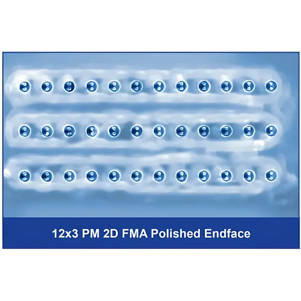
- End-face processing: Standard 8° angled polish (APC) minimizes back-reflection; flat (PC) and other angles (e.g., 0°, 12°) available upon request
- Robust packaging: 900 µm tight-buffered pigtails up to 2 m in length; optional connectorization with FC/PC, FC/APC, SC, or LC interfaces
- OEM-grade reliability: Designed and tested per Telcordia GR-1221-CORE (for reliability under thermal cycling and vibration) and GR-326-CORE (for mechanical durability and environmental resistance)
Sample Compatibility & Compliance
The 2D Fiber Optic Array is compatible with standard silica-based optical fibers compliant with ITU-T G.652.D (single-mode), G.655 (non-zero dispersion-shifted), and G.657.A1 (bend-insensitive). For polarization-sensitive applications, PANDA-type PM fibers meet IEC 60793-2-50 specifications and exhibit low PMD (<0.05 ps/√km) and PDL (<0.05 dB) across C+L bands. All assemblies undergo 100% visual inspection under 200× dark-field microscopy and insertion loss verification at 1310 nm and 1550 nm. Device-level qualification includes thermal shock (-40°C to +85°C, 500 cycles), humidity exposure (85% RH, 1000 h), and mechanical vibration testing (10–2000 Hz, 10 g RMS), satisfying requirements for deployment in GLP-compliant analytical instrumentation and telecom infrastructure.
Software & Data Management
While the 2D Fiber Optic Array itself is a passive hardware component, its integration into automated spectroscopic or metrology platforms benefits from standardized calibration documentation and traceable test reports. Each unit ships with a unique serial number-linked Certificate of Conformance (CoC), including measured insertion loss per channel (±0.1 dB resolution), PER values, and end-face inspection images. For OEM integration, Auniontech provides digital design files (STEP, Gerber) and mechanical interface specifications compliant with SEMI E10 and ISO 9001 documentation frameworks. Traceability supports FDA 21 CFR Part 11–aligned audit trails when deployed in regulated analytical workflows such as pharmaceutical QC spectroscopy or clinical OCT systems.
Applications
- Free-space-to-waveguide coupling in integrated photonic circuits and silicon photonics testbeds
- Input/output interfacing for miniature fiber-optic spectrometers used in portable chemical analysis and environmental monitoring
- Beam combiner/splitter arrays in Michelson and Mach-Zehnder interferometers for displacement metrology and surface profilometry
- Multi-channel excitation and detection in fluorescence lifetime imaging (FLIM) and confocal microscopy systems
- Optical switching fabric interconnects in reconfigurable optical add-drop multiplexers (ROADMs)
- Fiber-fed focal plane arrays in astronomical multi-object spectrographs (e.g., MOSFIRE, KMOS)
- Polarization-diverse signal routing in coherent optical receivers operating at 40 Gb/s, 100 Gb/s, and beyond
FAQ
What is the minimum pitch achievable for custom 2D array designs?
Standard pitches are 250 µm and 500 µm in X; 500 µm, 750 µm, and 1000 µm in Y. Sub-250 µm pitches are technically feasible but require evaluation of fiber handling risk and substrate manufacturability.
Can I specify mixed fiber types within a single 2D array?
Yes—hybrid arrays combining SMF, MMF, and PMF channels are supported, provided mechanical and thermal expansion mismatches are accounted for in the mounting design.
Is active alignment performed during assembly?
No—passive alignment using precision V-grooves ensures reproducibility and scalability; active alignment is available as an optional service for ultra-low-loss (<0.1 dB) critical channels.
Do you support custom connector ferrule geometries (e.g., MT/MPO for parallel optics)?
MT-type ferrules are supported for multi-fiber ribbon integration, though individual channel control is limited compared to discrete 2D arrays.
What documentation accompanies each shipped array?
Each unit includes a CoC, spectral insertion loss map (1310/1550 nm), PER report, end-face inspection certificate, and mechanical drawing package.