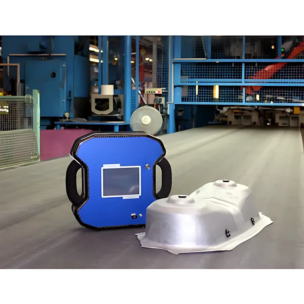
VIALUX comsmart Portable Grid Strain Analyzer
| Brand | VIALUX |
|---|---|
| Origin | Germany |
| Model | comsmart |
| Camera Resolution | 5.7 MP (standard), upgradable to 20 MP optics |
| Measurement Area (single capture) | 390 × 340 mm² |
| Node Processing Speed | 15,000 nodes/min |
| Calibration Time | ~3 min (fully automated) |
| Test Duration | 3–5 min |
| Strain Range | ≥100% (major/minor principal strain) |
| Output Formats | BMP, TIFF, PNG, JPG, VRML, PS, EPS (images) |
| Compliance | Designed for ISO/IEC 17025-aligned QA workflows, supports GLP/GMP traceability via audit-ready log export |
Overview
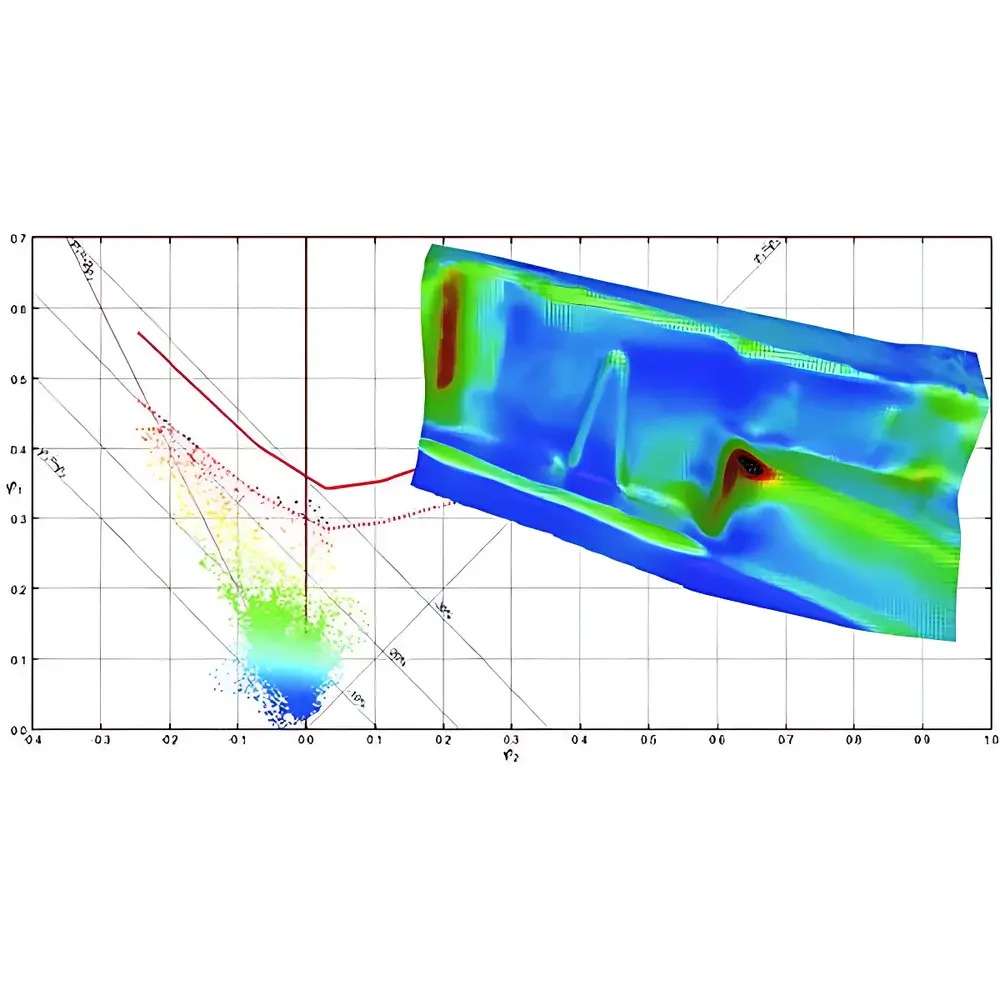
The VIALUX comsmart Portable Grid Strain Analyzer is a field-deployable optical metrology system engineered for full-field 3D surface strain mapping of sheet metal components following forming processes. It operates on the principle of digital image correlation (DIC) applied to pre-applied square grid patterns—typically electro-etched, painted, or printed onto the specimen surface. Unlike contact-based extensometers or single-point strain gauges, the comsmart system captures the complete displacement vector field across the deformed surface by triangulating sub-pixel shifts in grid node positions between reference (pre-formed) and deformed images. This enables quantitative derivation of major (ε₁), minor (ε₂), effective (εₑff), and thickness strain (ε₃) distributions with spatial resolution down to 0.1 mm per node—without physical contact, mechanical constraints, or post-processing interpolation artifacts. The system is purpose-built for integration into automotive stamping lines, aerospace component validation, and R&D labs where rapid, repeatable, and traceable strain assessment is required directly at the press shop floor or incoming inspection station.
Key Features
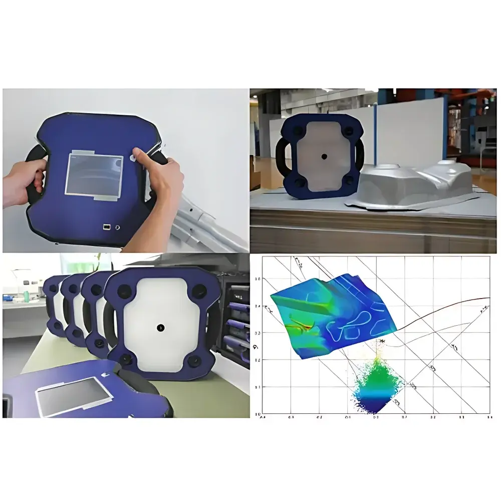
- Four rigidly mounted, synchronized high-resolution CCD cameras housed within a single compact test head—eliminating external mounting hardware, alignment jigs, or calibration targets during operation.
- Laser-assisted working distance control ensures consistent focus and depth-of-field across curved surfaces with local curvature exceeding ±90°, enabling reliable measurement on deep-drawn flanges, hemmed edges, and complex B-pillar geometries.
- Integrated high-brightness LED illumination with software-controlled exposure time and gain adjustment—optimized for reflective, matte, or coated surfaces without requiring spray-based contrast enhancement.
- Automated calibration routine completed in under 3 minutes using an adjustable reference scale; validated calibration remains stable over extended operational periods (≥72 hours) without recalibration—even after transport or thermal cycling.
- Real-time node processing at 15,000 nodes per minute delivers full-strain-field results within 3–5 minutes from image acquisition to FLD-compliant report generation.
- Modular hardware design: test head and calibration fixtures fit inside an IATA-compliant carry-on case (max. 55 × 40 × 20 cm), certified for air transport without special handling.
Sample Compatibility & Compliance
The comsmart analyzer accommodates specimens ranging from thin-gauge aluminum (0.5 mm) to ultra-high-strength steel (2.5 mm) and non-metallic composites (e.g., CFRP laminates). Grid pitch is user-selectable (0.5–5.0 mm), supporting both fine-resolution micro-strain analysis and macro-scale formability evaluation. Surface preparation requires only uniform grid application—no surface roughening, etching, or vacuum deposition is necessary. All measurement data adhere to ISO 10110-8 (optical surface quality), ASTM E837 (strain gauge calibration traceability), and ISO/IEC 17025 documentation requirements. Audit trails—including timestamped calibration logs, raw image metadata, and operator ID—are embedded in exported reports to support FDA 21 CFR Part 11 and GMP/GLP compliance frameworks.
Software & Data Management
The comsmart software suite runs natively on Windows 10/11 x64 platforms and features a zero-training-interface architecture: all functions—from camera triggering and lighting control to strain tensor computation and FLD overlay—are accessible via intuitive icon-driven panels. Image acquisition, 3D reconstruction, and strain calculation occur automatically; manual intervention is limited to region-of-interest selection and report customization. Export modules support direct interoperability with industry-standard simulation environments: ASCII tab-delimited files for custom scripting, native AutoForm and PAM-STAMP input formats for virtual tryout correlation, STL mesh outputs for reverse-engineering workflows, and DXF/AutoCAD-compatible geometry overlays for GD&T verification. All reports include embedded metadata (camera model, lens focal length, calibration date, ambient temperature) to satisfy ISO 9001 Clause 7.5.3 requirements for documented information control.
Applications
- Stamping process validation: correlation of physical part strain fields against virtual tryout simulations (e.g., AutoForm, LS-DYNA) to refine die design and blank holder force profiles.
- Incoming material qualification: batch-level verification of formability limits (FLC) for AHSS, aluminum alloys, and tailored blanks prior to production release.
- Failure root-cause analysis: localization of necking onset, shear band formation, and fracture initiation zones in crash-relevant components (A/B-pillars, rocker panels).
- Tool wear monitoring: longitudinal tracking of strain distribution drift across successive production lots to detect progressive die degradation.
- Research-grade ductility mapping: quantification of localized strain partitioning in multi-phase steels and functionally graded materials under complex loading paths.
FAQ
Does the comsmart system require adhesive markers or speckle patterns?
No. It relies exclusively on user-applied square grids—etched, printed, or painted—eliminating consumables, surface prep variability, and adhesion-related uncertainty.
Can strain measurements be performed on highly reflective or oily surfaces?
Yes. The adaptive LED illumination system includes polarization filtering and dynamic exposure compensation to suppress specular glare and maintain sub-pixel grid node detection fidelity.
Is the system compatible with existing CAE workflows?
Yes. Native exporters for AutoForm, PAM-STAMP, LS-DYNA, and STL ensure direct import into simulation pre-processors without format conversion loss.
How is measurement traceability maintained across multiple operators and sites?
Each measurement session generates a tamper-evident XML log containing calibrated camera parameters, environmental timestamps, operator credentials, and checksum-verified raw image hashes—fully auditable under ISO/IEC 17025.
What is the minimum measurable strain resolution?
System resolution is determined by grid pitch and pixel density; typical configuration achieves ±0.05% strain uncertainty at 1.0 mm grid pitch under controlled lab conditions (per VIALUX internal validation protocol V-COM-STR-003).


