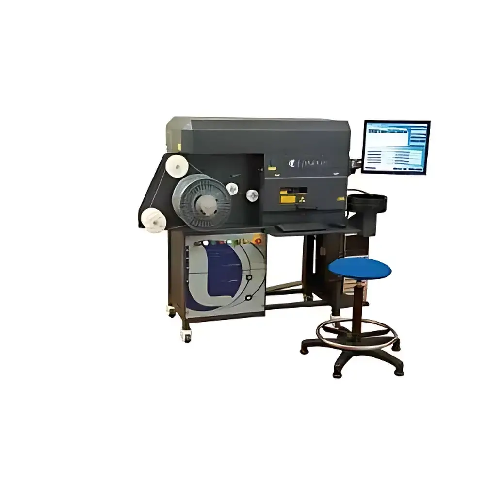
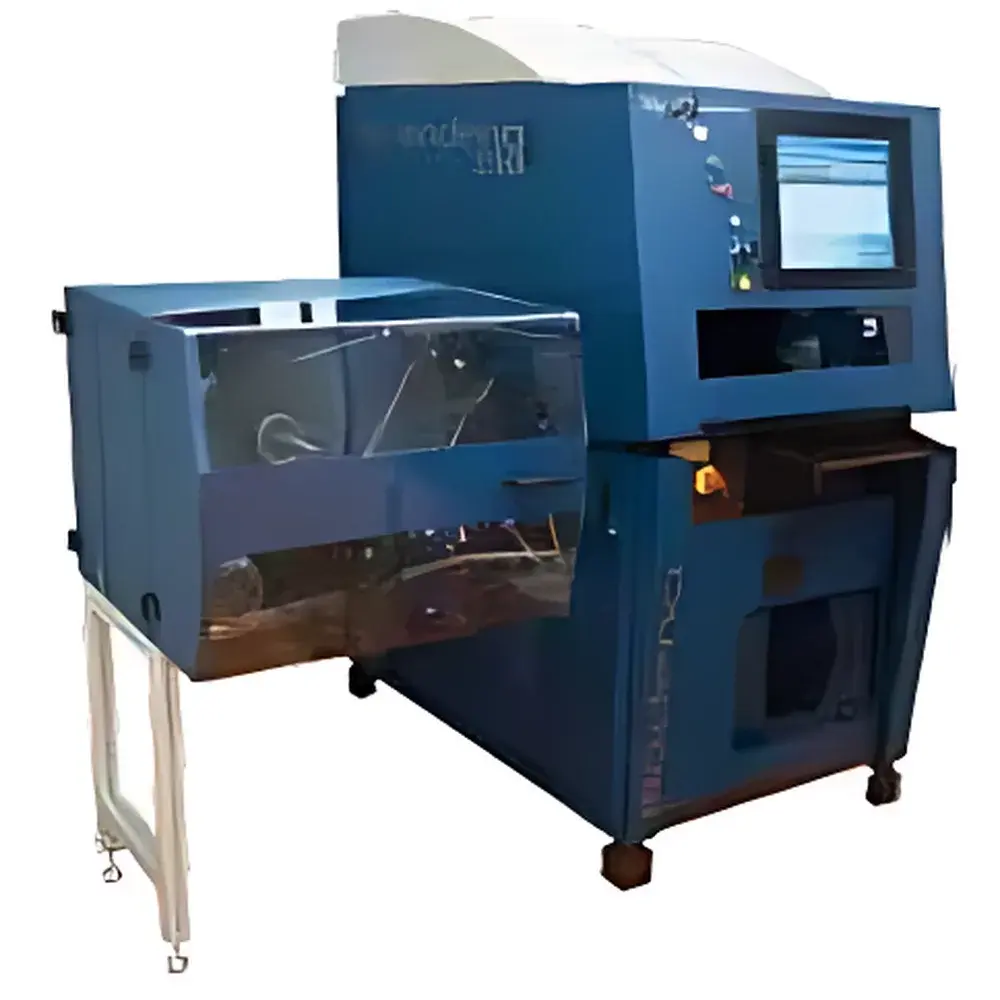
LASELEC MRO200 UV Laser Wire Marking System
| Brand | LASELEC |
|---|---|
| Origin | France |
| Model | MRO200 |
| Laser Wavelength | 355 nm (Third-Harmonic Nd:YAG Solid-State Laser) |
| Wire Gauge Range | AWG 6–AWG 26 (Ø 0.75–6.30 mm / 0.029–0.25 in) |
| Marking Length | 15 cm – 999 m (5.9 in – 3,277 ft) |
| Capabilities | Laser Marking + Precision Cut-to-Length + Automatic Spooling |
| Tension Control | Motorized Auto-Adjust |
| Fault Detection | Optical Sensor-Based (Knots, Breaks, Surface Defects) |
| Interface | Multilingual GUI with Integrated Production Management Software |
| Compliance | Designed for Aerospace AS9100 & IPC/WHMA-A-620 Requirements |
| Data Handling | Secure Upload/Download/Create/Delete of Job Logs & Traceability Records |
Overview
The LASELEC MRO200 UV Laser Wire Marking System is an integrated industrial marking platform engineered specifically for high-reliability wire and cable identification in aerospace, defense, and high-end electronics manufacturing. Operating at 355 nm—generated via third-harmonic frequency conversion of a solid-state Nd:YAG laser—the system delivers cold ablation marking with minimal thermal impact on polymer insulation, ensuring zero dielectric degradation or conductor deformation. Unlike infrared or fiber lasers, the UV wavelength enables high-contrast, permanent marks on fluoropolymer (e.g., FEP, PTFE), polyimide, PVC, and cross-linked polyolefin sheaths without surface carbonization or micro-cracking. The MRO200 is not a standalone printer but a synchronized production cell: it performs simultaneous laser marking, precision cut-to-length (±0.3 mm repeatability), and automatic spooling onto motorized reels—all under closed-loop optical feedback control.
Key Features
- UV cold-marking engine (355 nm) optimized for non-contact, non-thermal identification of delicate insulation materials including Teflon®-coated and fiber-optic cables.
- Integrated mechanical subsystems: servo-driven tension regulator, pneumatic shear unit with blade wear compensation, and programmable spooling mandrel with torque-sensing winding control.
- Real-time optical monitoring using high-resolution line-scan sensors to detect physical anomalies—knots, diameter deviations, insulation nicks, or conductor exposure—triggering immediate process halt and event logging.
- Self-calibrating laser head with dynamic focus adjustment; automatically compensates for variations in wire outer diameter (AWG 6–26) and insulation reflectivity across batch runs.
- Energy modulation algorithm ensures consistent mark legibility across heterogeneous cable assemblies (e.g., twisted pairs, shielded bundles, coaxial leads) without manual recalibration.
- Embedded industrial PC running deterministic real-time OS with deterministic I/O latency (<1 ms), supporting deterministic motion synchronization between marking, cutting, and spooling axes.
Sample Compatibility & Compliance
The MRO200 accommodates single-core wires, multi-conductor cables, twisted pairs, and jacketed fiber-optic assemblies with outer diameters from 0.75 mm to 6.30 mm. It meets critical aerospace marking requirements defined in AS9100 Rev D (Section 8.5.2 — Identification and Traceability) and IPC/WHMA-A-620E (Section 5.12 — Marking Requirements), including permanence testing per MIL-STD-130N Annex B (abrasion, solvent resistance, thermal cycling). All marking content—including part numbers, revision levels, lot codes, and QR-based UDI—is generated in compliance with ISO/IEC 15415 and AIM DPM-1-2019 symbology standards. The system supports audit-ready electronic records aligned with FDA 21 CFR Part 11 (electronic signatures, audit trails, role-based access control) when deployed in regulated environments.
Software & Data Management
The proprietary LASELEC Production Suite provides a browser-accessible HMI with multilingual support (English, French, German, Chinese, Spanish). It features recipe-driven job setup, version-controlled template libraries, and real-time SPC dashboards showing marking contrast ratio (measured via integrated grayscale photometer), cut length deviation, and spool tension variance. All operational events—including sensor-triggered faults, laser power drift corrections, and operator interventions—are timestamped and stored in SQLite-based local database with optional OPC UA integration for MES/ERP connectivity (SAP, Siemens Opcenter, Rockwell FactoryTalk). Data export complies with ASTM E2919-22 for traceability archive integrity.
Applications
Primary deployment contexts include: aircraft harness assembly lines (Boeing 787, Airbus A350), avionics box interconnect cable preparation, satellite harness prototyping, medical device cable labeling (ISO 13485-compliant), and automotive high-voltage battery harness production. The system is routinely used for marking wires prior to crimping, soldering, or connector insertion—ensuring full end-to-end traceability from raw material reel to final installed harness. Its ability to mark directly on extruded insulation—without pre-treatment or ink—eliminates VOC emissions and aligns with EU REACH Annex XIV and RoHS 3 directives.
FAQ
Does the MRO200 require periodic laser alignment or optics cleaning?
No—optical path is hermetically sealed and factory-aligned; maintenance is limited to scheduled inspection of focusing lens contamination and shear blade replacement per 500 km of marked wire.
Can the system integrate with existing MES or PLM platforms?
Yes—via standard OPC UA server (IEC 62541 compliant) or RESTful API endpoints for job dispatch, status polling, and log retrieval.
What level of operator training is required for routine operation?
Basic certification requires ≤4 hours; includes recipe loading, fault recovery, calibration verification, and daily validation per ISO 9001 clause 7.1.5.1.
Is offline marking mode supported for R&D or low-volume prototyping?
Yes—standalone “Mark-Only” mode disables cut/spool functions while retaining full laser parameter control, contrast optimization, and image-based mark verification.
How is compliance with aerospace traceability mandates verified during installation qualification?
IQ/OQ protocols include DQ traceability matrix mapping, contrast uniformity mapping across full AWG range, and simulated audit trail generation validated against AS9100D clause 8.5.2 evidence requirements.