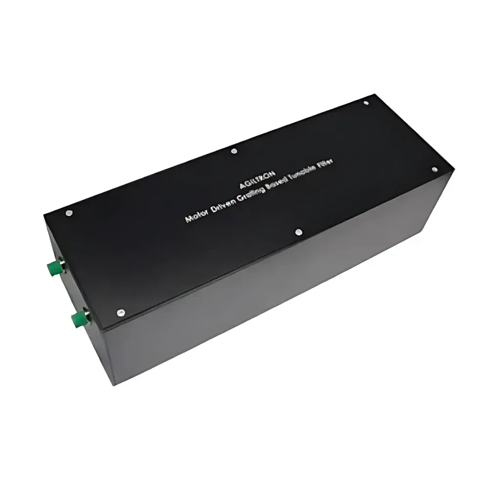
Agiltron MDTD Series Motorized Variable Optical Delay Line
| Brand | Agiltron |
|---|---|
| Origin | USA |
| Model | MDTD Series |
| Interface | USB & RS232 |
| Control Software | Windows GUI (PhotonWares) |
| Power Supply | 12 VDC / 1 A |
| Delay Range | up to 1200 ps |
| Repeatability | < 0.1 µm (sub-micron) |
| Insertion Loss | ≤ 1.5 dB (SM/PM, 1550 nm, connectorless) |
| Return Loss | ≥ 55 dB (SM/PM), ≥ 35 dB (MM) |
| Max Input Power | 20 mW (λ < 650 nm), higher-power versions available |
| Fiber Compatibility | SM, MM, PM |
| Drive Mechanism | Precision stepper motor with anti-backlash mechanism & proprietary optical encoder |
| Enclosure | Integrated driver electronics, compact monolithic housing |
Overview
The Agiltron MDTD Series Motorized Variable Optical Delay Line is an engineered precision instrument for controllable time-domain optical path length adjustment in free-space beam propagation. It operates on the fundamental principle of translating a retroreflecting mirror along the optical axis to modulate the round-trip distance traveled by a collimated beam—thereby introducing a precisely tunable temporal delay (Δt = 2L/c, where L is the variable free-space displacement and c is the speed of light in vacuum). Designed for integration into interferometric systems, coherence-gated imaging platforms, and polarization-sensitive measurement setups, the MDTD line delivers high stability, low insertion loss, and deterministic repeatability across its full delay range. Its optomechanical architecture eliminates flexure-induced phase drift and incorporates a custom anti-backlash translation stage coupled with a high-resolution optical encoder—ensuring sub-micron positional fidelity and long-term calibration retention without manual recalibration. The device supports broadband operation from visible to C-band (400–1650 nm), with intrinsic compatibility across single-mode (SM), polarization-maintaining (PM), and multimode (MM) fiber interfaces.
Key Features
- Sub-micron mechanical repeatability (< 0.1 µm) enabled by integrated optical encoder feedback and zero-backlash lead-screw actuation
- Delay ranges up to 1200 ps (equivalent to ~180 mm optical path difference), configurable in discrete models (330 ps, 660 ps, 1200 ps)
- Low insertion loss: ≤ 1.5 dB (connectorless, SM/PM at 1550 nm); optimized collimator design minimizes wavefront distortion and modal coupling
- High return loss: ≥ 55 dB (SM/PM), ≥ 35 dB (MM), achieved via angle-polished interfaces and anti-reflection coatings
- Native dual-interface control: USB 2.0 and RS-232 serial, supporting both GUI-driven operation and embedded UART command protocol (hexadecimal, 9600-N-8-1)
- Fully integrated electronics: onboard motor driver, position controller, and USB-to-serial bridge—no external motion controller required
- Compact monolithic housing (aluminum alloy, black anodized) with standardized mounting features (M4 tapped holes) for optical table or breadboard integration
Sample Compatibility & Compliance
The MDTD series accommodates industry-standard fiber types without modification: ITU-T G.652.D (SM), G.657.A1 (bend-insensitive SM), Panda-type PM fibers (e.g., PANDA-1550), and multimode fibers (OM1–OM5, core diameters 50–62.5 µm). For fibers with core diameters < 9 µm (e.g., visible-wavelength SM fibers), alignment sensitivity increases significantly—requiring precision APC or FC/PC mating and verified core-centering per IEC 61300-3-35. All units are assembled and tested in accordance with ISO 10110-7 (surface quality) and ISO 11146 (beam propagation parameters). While not certified to a specific regulatory standard, the design supports GLP-compliant laboratory workflows through traceable position logging, audit-ready software timestamps, and deterministic step-response behavior suitable for FDA 21 CFR Part 11–aligned data integrity practices when deployed with validated acquisition software.
Software & Data Management
Control is executed via PhotonWares™, a Windows-native GUI application providing real-time position monitoring (mm and ps), absolute referencing, multi-point scanning, and programmable dwell sequencing. The interface supports user-defined reference points (Ref 1/Ref 2), linear sweeps with adjustable step size (down to 0.1 µm) and dwell time (10 ms–10 s), and scan repetition (1–999 cycles). All motion commands generate timestamped log entries (CSV exportable) including target position, actual position, move duration, and encoder count delta. For automated integration, the UART command set enables direct microcontroller-level control—including position readback (0x01), absolute move (0x02), homing (0x03), and status query (0x04)—with checksum validation and timeout recovery. No proprietary drivers are required; standard Windows CDC ACM class enumeration applies.
Applications
- Polarization Mode Dispersion (PMD) emulation and compensation in telecom component testing per ITU-T G.698.2
- Reference arm modulation in Fourier-domain Optical Coherence Tomography (FD-OCT) systems requiring < 50 fs timing jitter
- Phase-stepping interferometry for surface metrology (e.g., Linnik or Mirau configurations)
- Time-resolved spectroscopy, pump-probe experiments, and quantum optics setups requiring synchronized optical delays
- Calibration of ultrafast photodetectors and streak cameras using known delay increments
- Lab-based dispersion characterization of chirped mirrors, grisms, and specialty fibers
FAQ
What is the minimum achievable delay resolution?
Positional resolution is limited by the optical encoder’s native step size (0.05 µm), corresponding to ~0.33 fs delay increment at 1550 nm. Practical resolution in closed-loop operation is ~0.1 µm (0.67 fs) due to mechanical hysteresis compensation.
Can the MDTD be used with femtosecond laser sources?
Yes—provided input peak power remains below damage thresholds. For Ti:sapphire (800 nm, 100-fs pulses), average power must be kept ≤ 50 mW and peak fluence < 0.1 J/cm² at the collimator input face. High-power variants with expanded mode-field diameters are available upon request.
Is thermal drift compensated during extended scans?
No active thermal compensation is implemented; however, the aluminum housing exhibits low thermal expansion (23.1 × 10⁻⁶/K), and positional drift over 8 hours at constant ambient (23 ± 0.5 °C) is < 0.3 µm (2 fs) after initial 30-minute warm-up.
Does the unit support triggering or synchronization with external equipment?
Not natively—the current firmware does not expose TTL trigger inputs or sync outputs. Synchronization must be achieved externally via software-timed command issuance or through third-party DAQ hardware interfacing with the UART port.
How is calibration traceability maintained?
Each unit ships with a factory calibration report referencing NIST-traceable laser interferometer measurements (Zygo Verifire™). End-user recalibration is not required under normal operating conditions; periodic verification against a stabilized HeNe interferometer is recommended annually for metrology-grade applications.