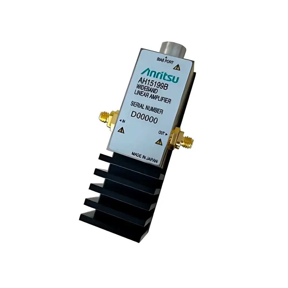
Anritsu AH15199B Broadband Linear Amplifier (200 kHz – 105 GHz)
| Brand | Anritsu |
|---|---|
| Origin | Japan |
| Model | AH15199B |
| Frequency Range | 200 kHz – 105 GHz (-3 dB) |
| -6 dB Bandwidth | up to 135 GHz |
| Small-Signal Gain | 15.5 dB (typ.) |
| Output Linearity | 2.0 Vpp (typ.) |
| Power Consumption | 1.5 W (typ.) |
| Input/Output Connector | W-type |
| Dimensions | 36 mm × 18 mm × 18 mm |
| Dedicated Power Supply | AH15199B-01 |
Overview
The Anritsu AH15199B Broadband Linear Amplifier is a high-fidelity, DC-coupled RF amplifier engineered for ultra-high-speed optical and electrical signal integrity applications. Operating across a continuous frequency range from 200 kHz to 105 GHz (–3 dB), with an extended –6 dB bandwidth up to 135 GHz, it delivers exceptional amplitude linearity and phase fidelity essential for next-generation coherent and intensity-modulated optical transmission systems. Designed specifically as a driver amplifier for 800G and 1.6T optical modulators—including both coherent IQ modulators and IM-DD architectures—the AH15199B enables precise, low-distortion waveform reproduction at symbol rates up to 140 Gbaud. Its architecture supports direct integration into test benches for high-frequency oscilloscopes, bit error ratio testers (BERTs), and arbitrary waveform generators (AWGs), where minimal group delay variation and flat gain response are critical for maintaining signal integrity in 400G ZR, Open ROADM, and OIF CEI-112G+ compliant systems.
Key Features
- Ultra-wideband operation: 200 kHz – 105 GHz (–3 dB), extendable to 135 GHz (–6 dB)
- High linearity output: 2.0 Vpp (typical) into 50 Ω load, supporting full-swing drive for lithium niobate (LiNbO₃) and silicon photonics modulators
- Low distortion design: Optimized for harmonic suppression and intermodulation performance under large-signal conditions
- Compact surface-mount package: 36 mm × 18 mm × 18 mm, compatible with automated RF probe station integration and modular test fixtures
- W-type coaxial I/O connectors: Ensures impedance-matched, low-reflection signal routing up to millimeter-wave frequencies
- Stable small-signal gain: 15.5 dB (typical) with ±0.5 dB flatness across the central 80% of its operating bandwidth
- Low power dissipation: 1.5 W typical consumption, enabling air-cooled deployment in dense instrument racks
- Dedicated regulated power supply (AH15199B-01): Provides ripple-free +12 V DC with overvoltage/overcurrent protection per JEDEC JESD78 guidelines
Sample Compatibility & Compliance
The AH15199B is validated for use with industry-standard 50 Ω RF measurement infrastructure, including high-bandwidth sampling oscilloscopes (≥100 GHz analog bandwidth), calibrated vector network analyzers (VNA), and photonic test platforms compliant with IEEE 802.3ck/cd and ITU-T G.698.2. It meets RoHS Directive 2011/65/EU and REACH Regulation (EC) No. 1907/2006 for hazardous substance restrictions. While not certified for safety standards such as IEC 61010-1, its low-voltage DC input architecture inherently complies with SELV (Safety Extra-Low Voltage) requirements when used with the AH15199B-01 supply. The device supports traceable calibration workflows under ISO/IEC 17025-accredited laboratories when paired with NIST-traceable reference sources and metrology-grade attenuators.
Software & Data Management
The AH15199B operates as a hardware-transparent analog signal path component; no embedded firmware or host software is required. However, it integrates seamlessly into automated test systems via SCPI-compatible instrumentation controllers. When deployed in production test environments—such as those governed by ISO 9001 or Telcordia GR-468-CORE—it supports full audit trail generation through external data acquisition systems logging voltage, temperature, and supply current at user-defined intervals. Its electrical characteristics remain stable under GLP/GMP-relevant thermal cycling (–10°C to +60°C ambient), and gain drift is characterized per MIL-STD-883H Method 1019 for long-term reliability assessment.
Applications
- Driving dual-polarization quadrature-phase-shift-keying (DP-QPSK) and 64-QAM optical modulators in coherent transceivers
- Boosting differential RF signals for electro-optic modulator bias control loops
- Serving as a broadband pre-amplifier stage in THz time-domain spectroscopy (THz-TDS) setups
- Enabling high-fidelity signal replication in multi-channel parallel optical interconnect validation
- Supporting compliance testing for IEEE 802.3dj (1.6T Ethernet) physical layer specifications
- Facilitating parametric characterization of photonic integrated circuits (PICs) under real-time modulation conditions
FAQ
What is the recommended termination impedance for optimal performance?
The AH15199B is designed for 50 Ω source and load terminations. Mismatched impedances may cause gain ripple and increased VSWR above 40 GHz.
Can the amplifier be cascaded with other broadband amplifiers?
Yes, provided inter-stage filtering and impedance matching networks are implemented to suppress passband ripple and avoid oscillation; stability analysis using S-parameter simulation is strongly advised.
Is the device suitable for pulsed RF applications?
It supports pulse widths ≥100 ps with <5% overshoot under matched 50 Ω loads, though duty cycle must remain below 15% to maintain thermal stability.
Does Anritsu provide calibration certificates with shipment?
Calibration data (S-parameters, gain flatness, output compression point) is supplied in Touchstone (.s2p) format upon request; NIST-traceable certification requires third-party lab engagement.
How does ambient temperature affect gain accuracy?
Gain variation is ≤±0.15 dB over –10°C to +50°C ambient, measured per MIL-STD-202G Method 107, with thermal stabilization achieved within 60 seconds of power-on.