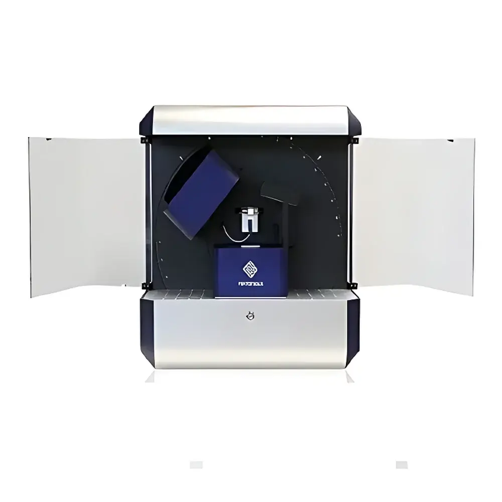
Appo MTA03 Integrated 3D Nanomechanical Manipulation System
| Brand | Appo |
|---|---|
| Origin | Switzerland |
| Model | MTA03 |
| Load Range | ±200 mN |
| Load Resolution | 0.5 nN |
| Displacement Range | 0.1 nm to 29 mm |
| Displacement Resolution (short-range) | 0.1 nm |
| Displacement Resolution (long-range) | 1 nm |
| Microscope Working Distance | 95 mm |
| Camera | 3 MP CMOS USB |
| Optical Zoom | 7:1 motorized |
| Illumination Options | Coaxial lens, ring light, diffuse backlight |
| Probe Types | Multiple FT-S microforce sensing probes |
| Optional Modules | FT-G microtweezers for microassembly |
Overview
The Appo MTA03 Integrated 3D Nanomechanical Manipulation System is a modular, high-precision platform engineered for quantitative nanomechanical characterization across soft and hard materials at micro- to nanoscale dimensions. Based on closed-loop piezoelectric actuation combined with MEMS-based force transduction and interferometric displacement sensing, the MTA03 implements a hybrid motion architecture: long-range (29 mm) stick-slip nanopositioning for coarse sample positioning and short-range (50 µm), sub-ångström-resolution piezo-scanning for high-bandwidth, low-noise mechanical testing. Its core measurement principle integrates load-controlled and displacement-controlled nanoindentation, quasi-static tensile testing, profilometric topography mapping, and in situ force–displacement–time analysis — all within a single instrument framework compliant with ASTM E2546, ISO 14577, and USP guidelines for nanomechanical testing of biomaterials and thin films.
Key Features
- Tri-axial nanomechanical manipulation with independent control over X, Y, and Z axes — enabling indentation, scratch, pull, bend, and shear testing under real-time optical observation.
- Force measurement range of ±200 mN with resolution down to 0.5 nN (9-decade dynamic range), achieved via calibrated FT-S series MEMS microforce sensors featuring temperature-compensated Wheatstone bridge designs.
- Displacement capability spanning eight orders of magnitude: from 0.1 nm (via piezo-scanner) to 29 mm (via motorized stick-slip stages), supporting both localized nanoscale probing and macro-scale structural interrogation.
- Digital microscope module with 95 mm working distance and ±90° tilt capability — eliminating occlusion by probes or microgrippers during multi-angle imaging and in situ test monitoring.
- Motorized 7:1 optical zoom and autofocus system, delivering field-of-view flexibility from 9.5 mm × 7.1 mm (low-mag overview) to 1.4 mm × 1.0 mm (high-mag detail), fully synchronized with stage motion and data acquisition.
- Triple-mode LED illumination: coaxial lens lighting for surface reflectivity enhancement, ring light for edge contrast optimization, and diffuse backlight for transparent or semi-transparent sample visualization (e.g., hydrogels, polymer membranes).
Sample Compatibility & Compliance
The MTA03 accommodates diverse sample geometries — including freestanding membranes, electrospun fibers, microfabricated cantilevers, PDMS elastomers, biological tissues, and brittle ceramic coatings — without requiring conductive coating or vacuum environments. Its open-stage design supports custom environmental cells (humidity, temperature, liquid immersion). All force and displacement calibrations are traceable to NIST standards; software logs include audit trails meeting FDA 21 CFR Part 11 requirements for electronic records and signatures. Test protocols align with ISO/IEC 17025-accredited laboratories’ validation frameworks, and raw force–displacement datasets are exportable in HDF5 and ASCII formats for third-party analysis (e.g., MATLAB, Python SciPy, OriginLab).
Software & Data Management
Control and analysis are performed using the FemtoTools Mechanical Testing & Handling Software Suite — a deterministic, real-time operating system (RTOS)-based application supporting synchronized acquisition at up to 10 kHz sampling rate. The software provides preconfigured test templates (nanoindentation, creep, stress relaxation, tensile ramp-hold, step-load profiling), customizable PID loop tuning, and automated tip geometry correction (Berkovich, spherical, flat-punch, wedge). Force–displacement curves are annotated with thermal drift compensation, frame-by-frame video synchronization, and metadata embedding (operator ID, timestamp, environmental conditions). Exported datasets include full calibration coefficients, uncertainty budgets per ISO/IEC Guide 98-3, and compliance reports for GLP/GMP audits.
Applications
- Soft Matter Nanomechanics: Spherical-tip indentation of hydrogels, lipid bilayers, and organoids to extract viscoelastic moduli using standard linear solid or generalized Maxwell models.
- Microfiber Mechanics: Tensile testing of electrospun SiO₂, silk, and cellulose nanofibers — quantifying yield strength, fracture strain, and time-dependent deformation under ambient or hydrated conditions.
- Thin-Film Characterization: Stiffness mapping of suspended diamond-like carbon (DLC), AlN, and nanocrystalline diamond membranes via 3D stiffness tomography and modal analysis.
- MEMS Device Validation: In situ bending, buckling, and adhesion testing of microactuators and RF-MEMS switches, correlating electromechanical response with structural integrity.
- Microassembly Support: Integration with FT-G microtweezers enables pick-and-place, alignment, and release-force quantification during micro-optical component integration.
FAQ
What types of indenter tips are supported?
Standard interchangeable tips include Berkovich, spherical (R = 1–50 µm), cube-corner, and flat-punch geometries — all certified per ISO 14577 Annex A and supplied with individual calibration certificates.
Can the system perform tests in liquid environments?
Yes — optional fluid cells with sealed optical windows and inert gas purging enable nanoindentation and tensile testing in aqueous buffers, organic solvents, or controlled pH solutions.
Is the microscope compatible with fluorescence imaging?
The base configuration does not include excitation filters or emission detection; however, the 95 mm working distance and modular lens mount allow integration with external epifluorescence or confocal modules.
How is thermal drift compensated during long-duration creep tests?
Real-time thermal drift correction is applied using dual-sensor referencing: one probe monitors stage thermal expansion while another tracks tip–sample contact point stability — both fed into a feedforward compensation algorithm.
Does the system support automated grid-based mapping?
Yes — the software includes scripting interface (Python API) for programmable grid navigation, auto-focus at each node, and batch processing of indentation arrays up to 100 × 100 points.


