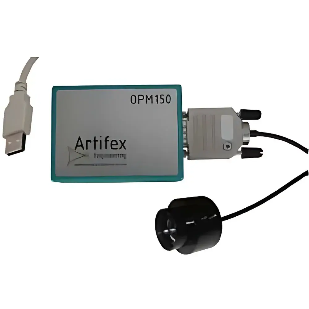
Artifex OPM1 Optical Power Monitor
| Brand | Artifex |
|---|---|
| Origin | Germany |
| Model | OPM1 |
| Type | Photodiode-based optical power meter |
| Measurement Range | 1 pW to 3 mW (typ.) |
| Wavelength Range | 190–1100 nm (Si), 800–1650 nm (InGaAs options) |
| Rise Time | 100 ns |
| NEP (RMS) | 7 µW |
| Output | Linear analog voltage (0–+4.5 V) |
| Interface | TTL-compatible modular control |
| Zero Offset Compensation | Up to ±7 V auto-zero |
| Compliance | CE, RoHS, ISO/IEC 17025 traceable calibration available |
Overview
The Artifex OPM1 Optical Power Monitor is a precision photodiode-based instrument engineered for high-fidelity, real-time measurement and monitoring of optical power across ultraviolet, visible, and near-infrared spectral bands. Operating on the principle of photocurrent-to-voltage conversion via a calibrated silicon or InGaAs photodiode, the OPM1 delivers linear, low-drift analog output proportional to incident radiant flux. Its dual-transconductance input stage ensures exceptional common-mode rejection ratio (CMRR > 100 dB) and linearity (±0.2% full scale) over its entire dynamic range — critical for closed-loop feedback applications in fiber alignment systems, laser diode stabilization, and component burn-in testing. Designed for integration into OEM platforms and laboratory-grade instrumentation, the OPM1 meets stringent requirements for reproducibility, thermal stability, and electromagnetic compatibility (EMC Class B per EN 61326-1).
Key Features
- High-sensitivity photodiode detection with selectable materials: Si (190–1100 nm), Ge (800–1650 nm), or extended-InGaAs (800–1650 nm) for application-specific spectral response
- 100 ns rise time (10–90%) enabling accurate capture of transient optical events in laser modulation and pulsed source characterization
- Integrated auto-zero circuitry compensating for DC offsets up to ±7 V — essential for isolating AC-coupled signal components during aging and reliability testing
- TTL-compatible modular interface supporting remote gain selection, zeroing, and channel enable/disable without external software dependency
- Compact mechanical form factor: Ø7.5 × 14 mm (free-space input) or Ø12 × 12.5 mm (fiber-pigtailed version), optimized for space-constrained optical benches and embedded subsystems
- Low noise-equivalent power (NEPRMS) of 7 µW at 1 kHz bandwidth, ensuring stable baseline performance under ambient light conditions
Sample Compatibility & Compliance
The OPM1 supports both free-beam and fiber-coupled optical inputs via standardized SMA905 or FC/PC receptacles. It accommodates continuous-wave (CW) and modulated sources including semiconductor lasers, superluminescent diodes (SLDs), and LEDs. Calibration is traceable to national metrology institutes (e.g., PTB Germany) and conforms to ISO/IEC 17025 requirements when used with certified reference standards. While not intrinsically compliant with FDA 21 CFR Part 11, the device’s analog output architecture enables seamless integration into GLP- and GMP-compliant data acquisition systems when paired with validated DAQ hardware and audit-trail-enabled software. All units comply with CE marking directives (EMC Directive 2014/30/EU and Low Voltage Directive 2014/35/EU) and RoHS 2011/65/EU restrictions on hazardous substances.
Software & Data Management
The OPM1 operates as a stand-alone analog sensor and does not require proprietary drivers or firmware updates. Its TTL control lines allow direct interfacing with programmable logic controllers (PLCs), microcontroller units (MCUs), or FPGA-based systems for synchronized gain switching and zeroing sequences. For PC-based integration, users may pair the OPM1 with third-party DAQ systems (e.g., National Instruments USB-6009, Keysight 34972A) supporting analog voltage input and digital I/O. When deployed in regulated environments, raw voltage outputs can be logged alongside timestamped metadata using 21 CFR Part 11-compliant software platforms such as LabArchives ELN or DeltaV DCS — provided the host system implements electronic signatures, audit trails, and role-based access controls.
Applications
- Laser diode output stabilization in telecom transceiver modules and pump laser assemblies
- Fiber-optic coupling efficiency verification during active alignment processes
- Real-time power monitoring in UV-curing systems and medical laser delivery devices
- Component-level qualification testing: LED luminous flux tracking, isolator insertion loss validation, and wavelength division multiplexer (WDM) channel balancing
- OEM integration into automated test equipment (ATE) for photonic integrated circuit (PIC) wafer probing and packaging
- Long-term reliability assessment of optical sources under accelerated aging conditions (e.g., Telcordia GR-468-CORE)
FAQ
What wavelength ranges are supported by the OPM1?
The standard OPM1 configuration uses a silicon photodiode covering 190–1100 nm. Optional InGaAs or germanium detectors extend coverage to 800–1650 nm; specific spectral responsivity curves are provided in the calibration certificate.
Can the OPM1 measure pulsed laser signals?
Yes — with a 100 ns rise time and flat frequency response up to ~3.5 MHz, the OPM1 is suitable for measuring quasi-CW and nanosecond-scale pulses where peak power remains within the 3 mW damage threshold.
Is factory recalibration required annually?
Calibration intervals depend on usage intensity and environmental conditions. Artifex recommends annual recalibration against NIST-traceable standards for applications requiring ISO/IEC 17025 compliance; stability data shows drift < ±0.5% FS/year under controlled lab conditions.
Does the OPM1 support fiber optic input with APC or UPC connectors?
The standard fiber adapter accepts FC/PC and SMA905 interfaces. Custom versions with SC/APC or LC/UPC receptacles are available upon request with corresponding calibration correction factors.
How is zero offset compensation implemented?
The auto-zero function applies a brief internal short-circuit cycle to the amplifier input, capturing residual DC bias and digitally subtracting it from subsequent measurements — effective for eliminating thermal EMF and photodiode dark current contributions.