Asphericon a|BeamExpander Series – Monolithic Aspheric Beam Expander / Reducer
| Key | Brand: Asphericon |
|---|---|
| Design Wavelengths | 355 nm / 532 nm / 632 nm / 780 nm / 1064 nm |
| Max Input Aperture | 10.6–14.7 mm |
| Max Output Aperture | 22.5 mm |
| Magnification Options | 1.5× / 1.75× / 2.0× |
| Cascadable Units | up to 5 |
| Diffraction-Limited Performance | individually measured & certified |
| Laser Damage Threshold (coated) | 12 J/cm² @ 100 Hz, 6 ns, 532 nm |
| Material | Fused Silica or BK7 (as specified) |
| Surface Figure Error (RMS) | ≤0.018λ @ 532 nm (single unit), ≤0.040λ @ 532 nm (5-unit cascade) |
Overview
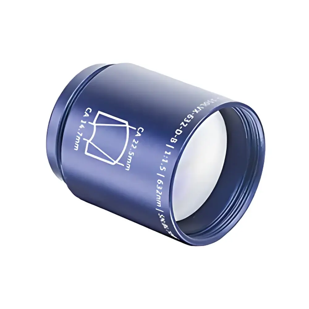
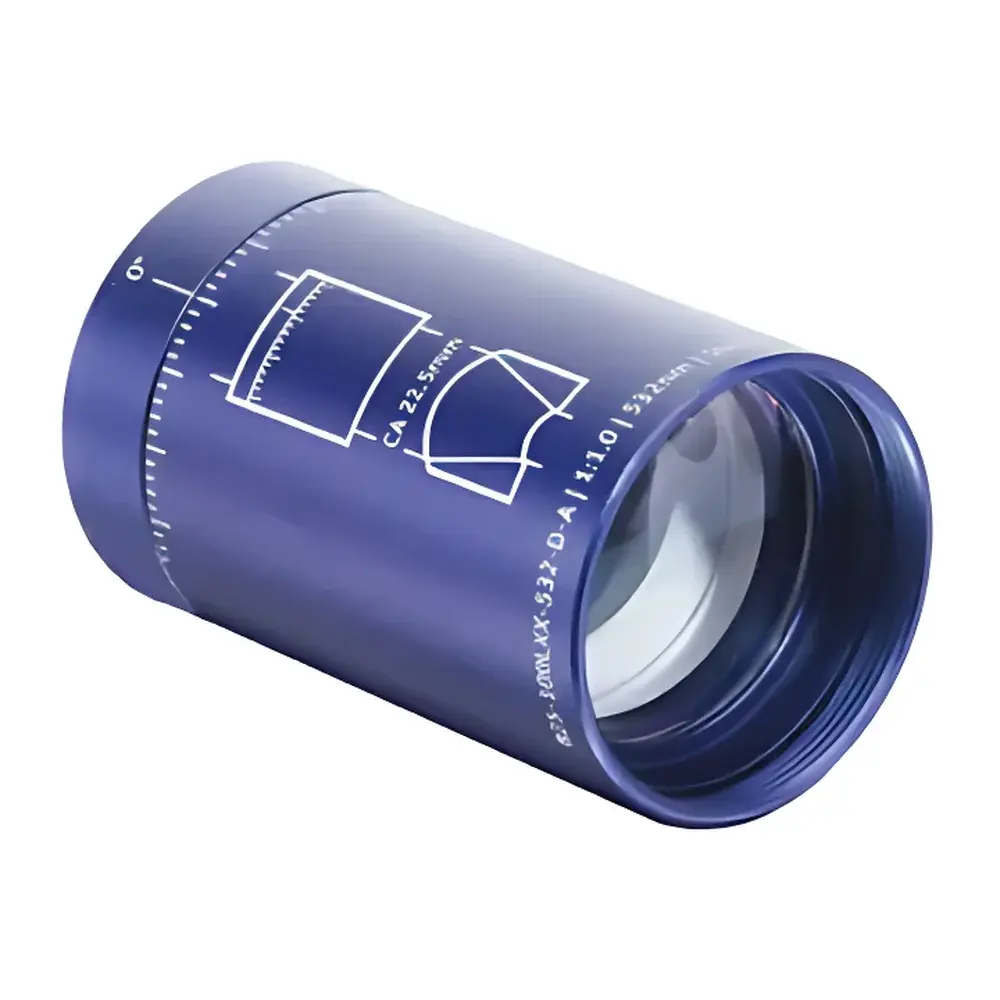
The Asphericon a|BeamExpander is a monolithic, single-element aspheric beam expander or reducer engineered for diffraction-limited performance in precision laser and optical systems. Unlike conventional refractive beam expanders based on multi-element Keplerian or Galilean designs, the a|BeamExpander employs a high-precision, rotationally symmetric aspheric surface fabricated from optical-grade fused silica or BK7. Its optical design eliminates internal reflections, chromatic aberration, and alignment sensitivity—enabling stable, wavefront-preserving magnification or reduction of collimated input beams across five discrete laser wavelengths (355 nm, 532 nm, 632 nm, 780 nm, and 1064 nm). Each unit is individually interferometrically verified and supplied with an Asphericon-certified test report documenting wavefront error (RMS ≤ 0.018λ at design wavelength), ensuring traceable metrological compliance for applications requiring ISO 10110–part 5 surface specification and ISO 14999–part 2 wavefront validation.
Key Features
- Monolithic construction with no air gaps or cemented interfaces—minimizing ghost reflections and group delay dispersion.
- Diffraction-limited operation confirmed via phase-shifting interferometry; RMS wavefront error ≤ 0.018λ (single unit) and ≤ 0.040λ (5-unit cascade) at 532 nm.
- Three fixed magnification options: 1.5×, 1.75×, and 2.0×—each optimized for a specific design wavelength and manufactured with sub-nanometer surface fidelity.
- Cascadable architecture supporting up to five units in series, enabling total beam expansion ratios up to 32× while maintaining system-level wavefront integrity.
- Laser damage threshold of 12 J/cm² (100 Hz, 6 ns pulse width, 532 nm) on AR-coated surfaces—validated per ISO 21254–1.
- Compact form factor with metric fine-pitch threading (M25×0.5 or M30×0.5, depending on model) for repeatable, kinematic mounting in OEM and laboratory environments.
Sample Compatibility & Compliance
The a|BeamExpander is compatible with collimated, spatially coherent input beams from CW and pulsed lasers—including Ti:sapphire, Nd:YAG, fiber, and diode sources—provided beam diameter remains within the specified input aperture range (10.6–14.7 mm). It complies with international optical manufacturing standards including ISO 10110–part 5 (surface irregularity), ISO 14999–part 2 (interferometric wavefront testing), and ISO 21254–1 (laser-induced damage threshold testing). For regulated environments such as GMP-compliant photonics R&D labs or medical device development facilities, the Asphericon certification package supports audit readiness under FDA 21 CFR Part 11 when integrated into validated optical subsystems. No regulatory exemptions apply; all units are CE-marked and RoHS-compliant.
Software & Data Management
While the a|BeamExpander operates as a passive optical component without embedded firmware or digital interface, its performance data is fully documented in machine-readable calibration reports (PDF + Zemax-compatible .ZBF files). These include measured wavefront maps, point spread function (PSF) analysis, and MTF curves at design wavelength—exportable for integration into optical design workflows using Zemax OpticStudio, CODE V, or FRED. For cascaded configurations, Asphericon provides vector Zernike coefficient sets enabling accurate prediction of cumulative wavefront error. Traceability metadata—including serial number, interferometer ID, operator signature, and environmental conditions during measurement—is embedded in each certificate to satisfy GLP documentation requirements.
Applications
The a|BeamExpander serves critical functions in high-precision optical systems where beam quality preservation is non-negotiable. Primary use cases include: interferometric metrology setups requiring stable, low-aberration illumination; adaptive optics wavefront correction chains; ultrafast laser beam delivery in CPA and OPCPA systems; confocal and multiphoton microscopy illumination paths; space-qualified telescope simulators; and industrial laser material processing heads where M² maintenance and focal spot stability directly impact cut quality and repeatability. Its compactness and modularity also support rapid reconfiguration in quantum optics experiments involving entangled photon sources and cavity-enhanced detection.
FAQ
Can the a|BeamExpander be used at wavelengths other than its designated design wavelength?
Yes—but only with the a|Waveλdapt compensator. Operating outside the design wavelength introduces defocus and higher-order aberrations due to mismatched aspheric coefficients and effective focal length shift. The a|Waveλdapt corrects these errors by introducing conjugate wavefront compensation, restoring diffraction-limited performance across 500–1600 nm.
What is the maximum permissible input beam divergence?
Input beams must be collimated to ≤ ±0.5 mrad divergence to maintain diffraction-limited output. Higher divergence degrades wavefront fidelity and increases RMS error beyond certified limits.
Is thermal drift compensated in the mechanical housing?
No active thermal compensation is integrated; however, the monolithic glass substrate and low-expansion mount design limit thermally induced wavefront drift to < 0.005λ/°C over the operational range of 15–30 °C.
How is alignment verified during system integration?
Each unit includes fiducial marks aligned to the optical axis within ±2 arcsec. Alignment is verified using shear plate interferometry or lateral shearing interferometers referenced to the input beam’s centroid and far-field profile.
Are custom magnifications or coatings available?
Standard magnifications are fixed at 1.5×, 1.75×, and 2.0×. Custom AR coatings (e.g., broadband 400–2000 nm or ultrafast-chirp-matched variants) are available upon request, subject to minimum order quantity and extended lead time.


